Sunday 26 October 2014

The blue smoke theory

One of my managers at work says that everything electrical and electronic requires blue smoke in order to operate correctly. He might be right. Have you noticed how when the blue smoke comes out of your laptop the laptop doesn't work any more? Or when the smoke comes out of your vacuum cleaner it also stops working?

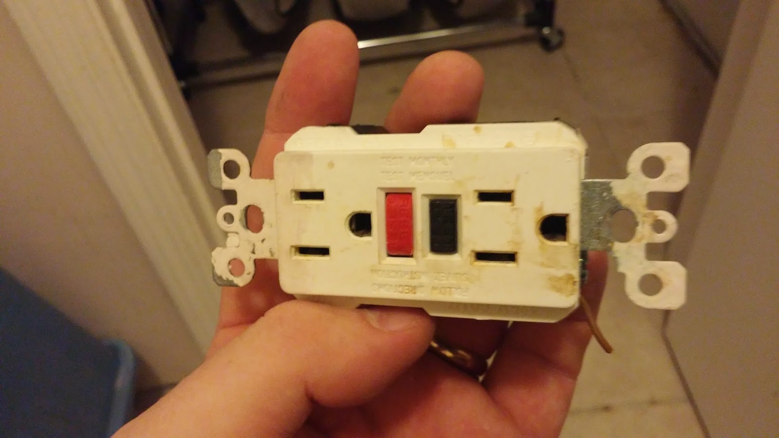
I had a similar demonstration of this theory today. The GFCI/ELCB socket in my downstairs toilet let it's smoke out today. Good job we caught it too otherwise we may not have had a home to live in.


Turns out that there was a loose connection in the return wire. Every time my wife ran her hair dryer it would cause the wires to move under the stress of the current load. The return (a white wire here in the US) would then disconnect itself then reconnect itself causing lots of sparks and arcing and burning. The result was that both the wires and the socket would get hot and so release their smoke.


Good job we caught it. Or rather my dog Rascal caught it. He heard the GFCI arcing then ran into the toilet and started scratching at the wall. It was only when he started barking drawing me into the room that I saw the problem. GOOD DOG!!!!! Extra belly rubs for you.


Monday 20 October 2014

Yaesu FT-817 Go Kit

Yeah, yeah, yeah. We've all seen Go Kits before. But as Go Kits go I think mine is "up there".

I am a fan of the Pelican case. Y'know the ones? Hard plastic water tight cases that can float and take a beating when traveling. They are usually filled with foam and have cutouts for the equipment they hold.


I bought an IM2200 from my local Best Buy electronics store for $100. This seems to be an average price for them. Ebay did not reveal a cheaper price. It comes filled with 2 layers of "pick-n-pluck" foam which allows you to create shapes by pulling squares of foam out.


In the above picture we can see the lower foam layer. I've created cutouts for the mic, mains PSU, PSU cable and antenna tuner cables. The small box in the top right corner is a Wolphi-Link interface. It's like a PSK31 sound card interface but for your cellphone/tablet. It will also get a cutout.


In this picture we can see the upper layer of foam which holds the FT-817, LDG tuner, spare battery, whip antenna and 1:1 balun. The egg box type foam in the lid also pulls out. I can get 25 feet of RG58 and a 50 foot dipole behind it and still be able to close the lid with ease.

Here's a video of me packing it all away into the case https://www.youtube.com/watch?v=NzgnMb5nZo8

Friday 10 October 2014

Mobile HF antenna install

I have a 2013 Dodge Journey. It's equipped with all bands from DC to light. It has FM, D-STAR, APRS and HF as well as a few non ham facilities. The problem with the car is that the steel its made from is very thin. The roof for example, flexes with the stress of a VHF antenna. So you can imagine what happens with a tall HF antenna?

A common HF antenna mounting solution is to install a clamp style bracket onto the rear liftgate high up as near to the roof line as possible. This is not possible with my car as the rear liftgate is made of plastic. Plastic and antennas don't work together. One needs a rather large amount of metal underneath the HF antenna so as to act as the counterpoise.

Over the 18 months or so that I've had my vehicle I've tried various mounting methods the best of which was a rather large magnet affair that consumed quite a bit of the roof space. This in turn prevented me from using the roof for other purposes.

My friend Kathy, KT2F, has an expression; "Be a man! I'm a man". She is referring to her willingness to drill holes in her new car to mount antennas. She's not wrong. According to my friend Norman, G4WQS, "a good mechanical join makes a good electrical join". Drilling a hole into the metalwork of the car would create both strong mechanical and electrical connections but only where the metal is thick enough.

I needed to replace the brake light on the back of my car today. Removing the light cluster is a simple matter of removing 2 plastic buttons. That's when I saw it. I finally found a spot to mount the antenna. It's not the best place on the car but it has all the other boxes checked.


You can clearly see the grommet where the cable exits the car behind the light cluster. By dumb luck I had a bracket in the junque box that would fit between the light and the car. 4 holes and some rivets later the mount was installed and a SO239 type antenna connector was attached to the mount. The coax feeding the antenna will feed through the grommet into the car and then on to the back of the radio.


As you can see from the completed installation, it is quite tidy. Click the pictures to get a closer look.


The total job took a little over an hour and that included fishing the coax cable from behind the interior paneling in the back of the car. Tests while parked on the drive show a much improved tune time (I have a screwdriver type antenna) and a broader bandwidth. Indeed, I no longer have to keep retuning when on 40 meters (the lowest band the antenna will cover) whenever I go from one end of the band to the other. Band-to-band tuning is also faster. I can now jump from 40 meters to 10 meters without the auto tuning circuit in the radio timing out.

So now I can tell Kathy that I'm "a man".

Saturday 27 September 2014

Weather satellite pictures update

It was a very fine autumn day today. I spent most of the morning up on the roof messing about with my antennas. One of these said antennas was for my newly built weather satellite receiver chronicled here http://g7ltt.blogspot.com/2014/07/apt-weather-satellite-pictures.html

There are still a few kinks to iron out of the system and computer control needs to be added but you get the idea ...


It seems the clock on my PC is a little off too. I guess I'll be digging into the bowels of RegEdit to force the NTP update to happen sooner.

Take a look at http://www.g7ltt.com/wxsat/ for more pictures and a timetable.

Wednesday 10 September 2014

GPS mini cape for Beaglebone Black

On a whim I bought a Beaglebone Black. Now what? I need more PC's like a hole in the head. So what to do with it? Nothing came to mind until I discovered one day that my home brewed NTP server had failed. Aha! A quick poke around the net revealed this howto. Stand well back folks.

I've been playing with the Ublox NEO-6x series of GPS receiver modules recently. They are super-simple to use and add to any project. They need only power, antenna and a serial port. So with the GPSRX being so small and simple to use a daughterboard or "cape" (why cape? UnderDog is a Beagle and he wears a cape) for the Beaglebone was a natural fit. (

The board consumes only one of the headers
The board sits on top of the BBB drawing power from it via the raw 5V line. I found that I had to increase the current on the 5V PSU that supplied the board so that I could get a reliable GPS lock but otherwise it worked first time. And as you can see below, my Linux terminal prefers it to the other available servers from us.pool.ntp.org

g7ltt@earth:~/Downloads$ ntpq -p
     remote                       refid            st t when poll reach   delay   offset  jitter
=====================================================================
*time.g7ltt.com             .GPS.            1 u    5   16  377    0.284    0.880   1.543
-tdp-ism01.exped    206.183.22.197   3 u    4   16  377   55.487  -61.764   1.003
+152-ism01.exped   129.6.15.28        2 u    9   64  377   31.547  -69.109   1.229
-upa-ism01.exped   206.183.22.197   3 u   15   64  377   43.276  -68.318   1.557
+810-ism01.exped   128.118.25.12    2 u    6   64  377   38.032  -67.287   1.023

The prototype board in service
The files in Eagle format ...


Friday 22 August 2014

20dB or 40dB RF Attenuator

I have found that I need an RF Attenuator for my bench. My bench tools are primarily suited to QRP work and so whenever I have to mess with a 35W FM rig I find that my meters and sensors are inadequate. I've killed quite a few bits of test equipment by stuffing 50W of RF into a 5W power meter.

As part of a larger project to create a 0-500MHZ power meter I started with the attenuator. There's nothing special about this one other than perhaps the compact design. It can be either a 20dB or a 40dB device dictated by the resistors you populate it with. Indeed, if you buy the boards from oshpark.com you can make both variations for less than $5.
See how simple it is?

The attenuator will present a 50Ω load to the connected radio and with its 1/4W resistors should be good for small bursts of around 50W of RF. Adding 1/2W resistors should increase the power capability to 100W and allow for longer key-up times at lower powers.

The files are listed below in both Eagle and PDF formats.

20-40dB_RF_Attenuator.pdf
20-40dB_RF_Attenuator.brd
20-40dB_RF_Attenuator.sch

Tuesday 5 August 2014

Credit card sized Arduino with Ethernet

I dunno about you but I find the whole Arduino board format very cumbersome. It can also get very expensive too. Frustrated with boards stacked on top of each other I decided it was time to create a smaller board format that housed my most common components: ethernet, I2C, 12v PSU and of course the micro processor itself. 

One can find anything on Al Gore's Interweb if one looks hard enough. It was not long before I discovered something that could be fashioned into use. It had a few minor issues but as I would have to design a board anyway it was a good jumping off point.

The completed board
My version differs from drj113's in that I have removed the DIP switches and replaced them with a dual header so that one can use the header for either analog inputs or as a DIP selector. I returned all the components back to normal size (some were SMD). I've also brought out all the unused digital pins to a header on the edge of the board and added a FTDI interface so that one may connect a serial programmer.

Well, it almost worked first time. I stuffed the PCB, uploaded a sample sketch that would connect to the Internet and .... nothing. Crap! I hate diagnosing circuits. But for some odd reason rather than get the meter out and poke on about the board I decided that the problem MUST be with the software. I get like that after a beer or 3.


I was kinda sorta right too! It would seem that there are in fact 2 different libraries for the ENC28j60 Ethernet chip I'm using and of course, I had the other one. Easily fixed. I edited the library source code to reflect the moving of one of the signal pins used by the Arduino to talk to the Ethernet. It appears that the 2 libraries exist because of the addition of an SD card reader. The SD card would share some of the same pins as the Ethernet. To allow for both, the Ethernet pins get moved around a bit. Great! I fixed it. Upload the sketch and ..... nothing. 

Well, not nothing but not anything useful. I had established communication with the Ethernet chip but no further. This was proved by the reading of the Ethernet chip's version number and then the failing of any DHCP. CRAP!!!!

It turned out to be a trivial fix in the end but it took me over an hour to diagnose; I had neglected to add a pull down resistor onto one of the Ethernet controllers pins. 2K7 later and bingo! It did not take long to correct the PCB files and re-upload them to oshpark for others to use.

The final board with all the bugs ironed out
I've already pressed this board into service with my NTP shack clock. It works great!!

The design files in Eagle format . . .


Bitx DDS and frequency display

I built a Bitx20. I'm not happy with it. The VFO leaves much to be desired and whilst many folks find it acceptable I find it cumbersome and inexact. I never know what frequency its on. It appears that many users find this to be the case as is evidenced by the handful of digital VFO addons for the Bitx. Time to build my own.

So what do I want mine to do? Well, let's see . . .
  • Arduino based (because it's easy)
  • LCD readout
  • Use cheap Ebay 9850 DDS module 
  • CW keyer with paddle input
  • FT-817 style computer control
  • Channel buttons
  • S Meter and battery voltage etc.
  • Probably other things too
And here it is! It did not take too long to create. I borrowed much of the Arduino code from  other projects and hacked it all together.

The finished board
Observant bastards will have noticed the MIC and PTT inputs on the upper right of the board. This allows the PTT from the Mic to be wired through the board. The board will then compare the current frequency against it's internal band plan and then key the rig (or not). It will also display a TX or RX symbol on the readout.

The LCD readout showing the current frequency (upper line), battery volts (lower left), step rate (lower middle) and S-meter reading (lower right) 

The board under test

The IF + VFO combined output

Thursday 24 July 2014

The packet racket

I'm working with a small group of other hams trying to get some Packet Radio links operational again. You would think that after 30 years of this mode there would be an easy, turn key method with which to get it all going. Think again.

One of Packet's problems is that it was more-or-less abandoned in the mid 90's when the World Wide Web came along. So the only stuff that one can get for this mode is of that vintage.

APRS on the other hand uses Packet Radio and is very successful. But still there are few to none turn key kits available for this variation of Packet.

It would seem that I'm not the only one thinking that this should be easier. I went looking for a TNC (Terminal Node Controller) that I could attach to the USB port of my computer. This was a mammoth task in itself. With newer machines leaving "legacy" connections behind, Ethernet and USB are the order of the day now. No more serial ports.

Then I happened upon SP9UOB's dsTNC. It is a dsPIC (a PIC that does DSP). It has all the makings of a low cost, easily constructed TNC. It can do 1200bd (the current data speed) and has aspirations on 9600bd with a firmware change.

SP8UOB's original drawing

Looks simple right? Problem is that it has a "proper" serial port. No USB.  That I can fix. I've been doing lots of stuff with the FT232 USB-Serial converter chip lately so I added on to this design.

My version of the TNC
So I then designed a circuit board. 2 in fact. One using "normal" sized components and the other using SMD parts. There were a few things wrong with it but nothing that a few "green wire links" couldn't fix.

The PCB I designed
The test board
Then came time to plug it in. The firmware has a terminal interface to aid in setting up things like your call sign and the PTT delay etc. It also has a KISS mode. I connected it to a radio and tuned to the local APRS channel. Lots of lovely APRS positions came spooling in to my computer. It works!!

But I don't want to use it for APRS. I want to use it for normal Packet operations. In support of this the device supports the KISS mode. This mode allows the user to operate the device in a manner not unlike a normal modem; the attached computer will do all the work.

It does NOT work! Well, that's not quite true. It does support KISS and works just fine if all you want is an APRS modem. But a TNC is more than a modem. It has a CPU, RAM,Modems etc. What I found was that if the passing data packets were of a certain length they would be decoded. If they were shorter or longer they would not be decoded. This is flat no use with normal Packet operations.

After much gnashing of teeth and questioning of known working equipment I tracked down the problem. The firmware was not correct. The "TNC" part was not there. 

I advised SP9UOB of my findings and he in turn sent me a patched version of his firmware. Indeed this worked - sort of. I could now decode passing data of any size but if the data was too long it would arrive garbled or even be missed altogether. SP9UOB has not selected the correct micro processor part and so it did not have enough RAM to store/decode the passing data. So it still doesn't work as I'd hoped it would. 

Back to the drawing board!

Design files are in Eagle format in case you want to have a go yourself.
dsdigi_v124.hex
dsTNC.brd
dsTNC.sch
dsTNC-smd.sch
dsTNC-smd.brd

APT weather satellite pictures

Back in the late 90's I realised a long term goal. I bought and built a weather satellite receiver. The kit was developed by a group called RIG (Remote Imaging Group) and sold for around £100. A good few thousand of these kits were sold worldwide. I even bought more of them to give away to local schools.

Its now 2014 and this kit has run its course but look closely on Ebay and you'll see that they are still available. RIG has been selling them for a closeout price of £50 plus shipping. As I had given away my last one to UACNJ I grabbed me another kit.

The finished kit in its new housing

I also made a few modifications. The kit would normally have a single 7 segment LED to indicate what channel it was tuned to. You could also add a signal strength meter to give you some idea as to how well you were hearing the satellite. I decided that I wanted a LCD rather than an LED. It would make the project look a little more modern. To that end I designed a LCD interface around an Arduino. I drew heavily from the work of Grant Zehr, WA9TFB. Grant had earlier designed a similar LCD display based on a PIC16F84 but it was limited to displaying only a few channels because the chosen PIC was lacking input and so could not read the entire state of the LED. The Arduino doesn't have that problem.

The Arduino LCD expansion board

In addition to the LCD expansion board I created a breakout board to better handle the large wiring loom that connects all the controls to the actual receiver. This board also manages the master power switch as well as supplying power to the LCD board.

The breakout board

To my surprise it all works! I've not finished putting holes in the enclosure yet but the receiver and display work very well. I have populated the channel table in the Arduino with some information about the satellite that is on a given channel so that one can see more than just "4" or "9". The Smeter is also displayed as a bar graph on the lower left of the display when receiving a satellite.

The whole project undergoing testing

Looking for satellites

The next step is to connect it up to a spare PC so that I can display the actual pictures the receiver gets. I'll make these available on my website too.

Wednesday 23 July 2014

A new clock for the shack

Segal's Law states :

"A man with a clock knows what time it is. A man with 2 clocks is never sure."

It speaks to having too much information when making a decision.

I have that problem. I have a thing for building electronic clocks. Nixie's, LED, LCD, Binary, VFD. I have them all. I have never built one of my own design however. They have always been found on the Internet and built from a diagram or around a PIC etc.

This clock is different. I can honestly say that I designed it from scratch. I wanted an NTP based clock so that it would always be correct without me having to set it every time the power went out. I also wanted to learn how to use an Arduino. This clock was born out of a combination of those two needs.

In addition to displaying the current UTC time the clock also displays the current cycle of the HF Beacon Project.


I love this picture ....

I'm a member of UACNJ, an astronomy club in Hope, NJ. We are open to the public every Saturday night from April until the end of October. It was one such night last year when I took the below picture. I was standing with my back to the 'scope when I heard a child screaming. I turned around and saw this Praying Mantis on the finderscope. He was very obliging and waited for me to find my cell phone so that I could take his picture.

Who put the cat in the wash?

Our other cat Snowball, likes to hang out in odd places. I went to load up the washing machine the other day only to discover he was already in there. I wonder if I need to put him on a "whites wash"?

Snowball sleeping in the washing machine.
Update 09/10/2014

It is with regret that I report the passing of Snowball. Unfortunately Snowball perished in the washing machine he loved so much. A load of laundry was done and he was not noticed in the machine. His remains were discovered by my daughter some hours later.  Snowball now rests in the garden where he can dream of chasing chipmonks all day.

Cats in my pants

We have 2 cats. They belong to my wife and daughter. But yet some how they always want to be with me. They follow me everywhere. Including the bathroom. Can't a bloke take a crap in peace?

Boots curls up in my underwear whilst I'm taking a crap.

Weather station back online

After an almost 4 year hiatus my Davis Vantage Vue weather station is back online. Point your browser to http://www.g7ltt.com/weather for a closer look.

The very first blog posting ever. Well, for me anyways.

Hello folks!

Many of you have noted that there has not been much activity in my web space of late but yet there are all sorts of activities going on in my shack. Truth is I cannot be bothered with all the faffing about that used to be writing web pages. All that code and links etc just get tiresome in the end.

So, I'm going to have a go at this thing. Don't expect daily updates or anything. This will simply be a place to do a brain dump. It'll make sense or it won't.

Thanks for sticking with me and stay tuned!

Mark