Thursday 30 November 2017

Funny things you see at Microcenter

So I was at my local Microcenter this lunchtime and I saw this on display. It might be a little "wishful thinking" But I get where they are going.


Yep. You read that right. Apparently Microcenter think that Death Stars are "emerging technologies". I wonder when they'll start selling flying cars?

Friday 10 November 2017

Mic interface for RemAud

In a previous article I built a simple isolated audio interface to go between my radio and a PC for remote operation of the radio. This time I built an interface so that I could use the microphone from the radio on the remote PC 3 floors away.

I decided to use the mic from the HF rig as this would give the most accurate user experience. The user would simply pick up the microphone, press the PTT button and speak. The interface also has a USB to serial interface which allows the PTT to inform the computer that the user is in fact speaking.


And of course I designed a PCB for it. You can get it at Oshpark


Simply connect normal sound and usb cables from this interface to your PC and then plug your Yaesu dynamic mic into the other side. Tell RemAud to use the CTS line of the new USB-serial interface.

I've added an audio buffer with a 300hz filter to clean up the mic a little. This might not be needed and so you can simply omit most of those parts and jumper across from the junction of C4 to C6 but do leave C6 installed as there is DC power coming from your PC to power an electret mic.

Feline hunting

There are many cats that inhabit my house. None of them are mine. This one is Dee. She's a black and white Domestic Shorthaired cat and she has caught a mouse. It's still alive. If this was a video you'd see the mouse panting with fear. I caught this mouse and released it back outside.


An hour or so later I was driving down my street returning from a shopping errand when I saw her again. This time she's got something much bigger. She's nabbed a squirrel.


Turns out that this is not Dee but rather her neighbourhood doppleganger. We've taken to calling this cat "Double Dee". There you go Dee. That's how you hunt! Next time bring something home that we can all eat.

Isolated sound card interface

I've been working towards getting my girlfriends HF rig remotely controlled. We have it installed in the sun room at the back of the house but her office is up in the attic on the 3rd floor.  This presents a problem as not only do we need to control the radio but we also need to hear what it receives and also send it some audio to transmit.

The radio control is easily achieved by using Ham Radio Deluxe and is very well documented elsewhere. For the audio portion I am using RemAud by DF3CB which is also very well documented on his website. What's not so well documented is the hardware that one might need be able to both receive and transmit audio from another location. It should be noted that whilst I am doing this from another room 3 floors away it could equally be done from 3000 miles away over the Internet.

If you are familiar with Skype then you'll know that it uses the sound system installed into your PC. The microphone is usually sourced from your webcam and the speakers let you hear the other person. RemAud is a similar application. It uses the same audio sources. And that's where the difficulty begins. Your HF rig cannot use the mic on your webcam.

Luckily this problem has been solved many times before. A simple radio-computer sound interface is all that's needed on the radio end. It needs to move audio from the PC to the radio and back. It also needs to key the PTT to enable the radio's transmitter. This is what I came up with.


It's an isolated audio interface with USB based PTT keying. I made it from the junk box. The Audio part is a copy of the many transformer based sound card interfaces one can find on the 'net. The transformers isolate the electrical path between the radio and the computer in an effort to reduce computer noise getting into the radio.


The USB part is a USB to serial interface that I had meant to use in an Arduino project but never got around to it. I added a small bit of circuitry to invert the signal from controller chip and also isolate the PTT from the computer.

I also added a USB sound card adapter to the PC to manage the sound instead of using its built in sound facilities. I'll be moving it all to the rear sockets of the PC and there are no sound outputs there.

It works very well. However, I am not happy with it. The PTT should really be isolated via a opto-isolator and it's larger than I'd like. So I set about designing another interface. This time it's more compact and has "proper" sockets etc. It's also fully isolated and can also key some CW too.


I designed a board for it too. You can get it at Oshpark


And here's the finished result. It works perfectly. It's also much smaller and now fully isolated. I used a PS/2 male-male extension cable that I got from Microcenter to connect the data port on the rig to the interface. At $8 it was not worth my time or effort to try soldering a cable myself.


There was a caveat that took me a few days to work out. Direct from the factory the FT232 USB-serial chip has its signals inverted. This is correct as it actually converts from TTL to USB, expecting another chip to do level shifting up to the +/-12v that is RS232. But the chip makers have thought of that. They have a tool on their drivers website that allows you to change the signalling on any of the pins. I inverted DTR and RTS so that they would go high when applied thus powering the LED in the opto-isolator. 

The Bill Of Materials is quite trivial;

  • FTDI FT232RL USB to Serial chip x1
  • 10K x1
  • 1K x3
  • 3MM LED x1
  • 0.1uf x2
  • 10uF x1
  • Mini-USB 'B' x1
  • 4N25 x2
  • 3.5mm audio socket x3
  • 42TM016 600:600 audio transformer x2
  • PS/2 6 pin mini DIN socket x1

Monday 23 October 2017

Remote control of your radio via "CAT"

I've moved into a new house. The only room in the house conducive to radio is a conservatory or sun room at the back of the house. But It's not ideal for all the trappings of ham radio and so I looked into some sort of remote control over my house data LAN from my study in the attic.

I'm not going to document here what I did but I used Ham Radio Deluxe on a small footprint Windows PC and was able to remotely control it with HRD installed on my Linux box. It all works like a dream. It uses something called CAT or Computer Aided Transceiver which is just a fancy way of saying that the computer can control the radio.

Well, works like a dream might be a bit of a stretch. It _was_ working like a dream. Then suddenly it stopped working. So I descend the 3 floors down to the sun room only to discover that the radio was being controlled by a different sort of CAT.


Meet Elvis. He likes to sit on electronics. I assume it's because they get warm?

Saturday 2 September 2017

Folding Solar Panel

I own a 120W solar panel which is great for recharging my batteries when I'm camping and doing outdoor radio activities. The problem with it is that it's too big. I cannot get it into my car easily. So the obvious thing would be to get a smaller panel. OK, but smaller means less power and oddly, they are more expensive than larger ones when converted to "$$ per Watt".

The obvious solution was to buy a folding solar panel. It would deliver the power I want and also fit into the car. However, have you looked at the price of folding panels? They run about 3 times the price of a non-folding one at the same power output. No thanks.

So what to do? How about I build my own!


So that's what I did. I was able to source some 40W panels from Amazon for $55 each including shipping. A continuous or "piano" hinge, a pair of sash window locks and a handle were all that was needed to complete this project.


Here we see the back side of the panels. I used the hinge as a template to drill holes for the rivets I used to secure the hinge to the panel. Once the hinge was installed it was on to the wiring. The panels had a nice box on the back where the connections were made. Opening the box revealed 2 screw terminals. It was a simple job to add a pair of ring terminals to one of the wires and connect it to the other panel's junction box.


So what was the point of making this? Look at the picture below. This is me and my telescope equipment. I took my family to see the Great American Solar Eclipse (August 21st 2017). Powering their devices and all of my telescope gear, laptops etc took quite a bit of power. I was able to do this by using a large deep cycle marine battery and this solar panel (and the relevant charge controllers etc). Look closely just below the bottom left corner of the black box housing the laptop. You can see the panel on the ground.


Wednesday 16 August 2017

Solar powered GMRS repeater

I recently made a solar powered GMRS repeater for use on a remote farm. The largest building on the property is the barn and so this was chosen as the home for the machine.

So this is the almost finished repeater mounted onto the wall of the barn. There are still a few jobs to complete such as running the antenna coax and mounting the solar panel outside. We ran out of time before the summer storms came and we had to go home. Luckily we'll be back there shortly so can finish it up.


It's a simple setup consisting of 2 UHF Motorola SM50's, a "mobile" cavity filter, Raspberry Pi 3 running SVXLink repeater software, solar charge controller, 35 Amp lawn mower battery and various wires and connectors. Oh, and a solar panel and antenna. Total cost for this machine was about $325.


Saturday 29 July 2017

ACME fails again ...

Here in the DE/MD/NJ/NY/PA area of the US we have a supermarket chain called ACME. I swear to Bob that it is run by idiots!

I spotted this in my local store recently.


It's a recall notice. It tells of a product recall for a chicken nugget food item. But look behind it on the shelf (click the pic to enlarge). It's the very same item that has been recalled!!!!

Tuesday 25 July 2017

3D printed Anderson Powerpole distribution box

I have a Robo3D 3D printer which I'm having a lot of fun with. I'm also trying to build a GMRS repeater for use on a farm. I laid out all the hardware only to discover that I needed a tidy way to distribute the power to the various devices.

The repeater being laid out on a 2'x2' piece of 3/4 plywood
Meet the Parametric PowerPole Breakout Box which can be found here on Thingiverse. The Parametric part comes from the way in which you can create anything from a 2 port to an 8 port box.


I printed a 4 port box. As you can see, it has 6 ports. No my printer did not do it wrong. The ports at either end allow the power to be connected to the box without loosing one of the 4 ports. One can also stack the box together to make larger boxes. In the above pictures I've assembled the connectors the wrong way - DOH. Luckily I caught it before I soldered it all together.


That is #12 solid electric wire connecting the PowerPoles together. I pulled the ground wire from a small run of Romex household electrical wire and used it to connect things together. The joins were wrapped and soldered and the ends were crimped and soldered.

Depending where you get them from PowerPoles can be as much as $2 a pair so using that price as a guide (I buy mine in bulk and have them on hand) I managed to construct this box for about $15 including the price of the PLA 3D printer material, electricity etc. Not too shabby!!

Schrodinger's Cats?

What is it about cats and boxes. Every time you put an empty box down onto the floor it becomes immediately inhabited by a cat. Or does it? 😉 Perhaps this was what captured Schrodinger's imagination and shaped his ideas on Quantum Physics?

For the cat lovers out there, here is a collection of just a few of the cats that inhabit my apartment. Please understand that they are not _my_ cats. Indeed, one of the cats has another cat as his pet.

Elvis
Gracie
Boots AKA Orange Dog


Gracie

For his next trick, Boots will make a girl disappear

Rascal. He's a Lhasa Apso with a Doberman complex. The cats are bigger than him.

Wash my clothes in what?

Found at the local Korean supermarket


My girlfriend asked if they had any Dragon dung but this was the closest they had.

Wednesday 14 June 2017

Programming the Motorola SM50 under Linux

The Motorola SM50 and SM120 are quite a common radio and pop up on eBay all the time for modest prices. As with all Moto gear they come in a variety of models; wideband, narrowband, 2 channel, 16 channel, 40 watt, 4 watt etc etc etc. There are various model decoders available around Al Gore's Interweb Tubes so we won't be covering that here.

I am the proud owner of quite a pile of SM120 M44DGC20C2AA (40W UHF high wideband) models which are ideal for a repeater blabber box, GMRS or FirstResponder use such as your local Ambulance Squad.

Programming them back in the early 90's (yep, they are even older than that!) was by way of a DOS program running on a lowly i286 PC. But hold on, we are on Linux. How's that gonna work? Take a quick look at this youtube video ...


Things you'll need:

A Linux box (DUH!)
DosBox emulator software (apt-get install dosbox)
SM50 programming software (can't help you there but it's not hard to find)
Motorola GM300 style programming cable or "RIB" (I use a USB one from ebay)

How to do it:

Using your favourite terminal program (I use Yakuake) fire up the dosbox emulator by typing 'dosbox'. If you have a Z: prompt then that part works.

Unpack your SM50 software into a folder. Navigate to that folder and then fire up your favourite text editor. we'll be making a config file called 'sm50dosbox.conf'. Mine looks like this ...

[cpu]
core=auto
cputype=auto
cycles=191
cycleup=10
cycledown=20
[serial]
serial1=directserial realport:ttyUSB0
serial2=dummy
serial3=disabled
serial4=disabled
[dos]
xms=true
ems=true
umb=true
keyboardlayout=auto
[autoexec]
# Lines in this section will be run at startup.
# You can put your MOUNT lines here.
mount C /home/g7ltt/raid/Filestore/DOS
mount M /home/g7ltt/raid/Filestore/motocd/SM50/R030000
m:
m:\SM50.EXE
Adjust the 'serial' lines to match your USB port. Also adjust the 'mount' lines to reflect your path. In my case 'C' becomes C: and holds a few DOS utilities. The 'M' becomes M: which contains my SM50 software. 

Save your file and the type 'dosbox -conf sm50dosbox.conf' and watch it all fire up. You'll have to configure the dos software to use COM1 but otherwise you'll be programming in no time.

In theory this should work for other Motorola DOS based programming tools for other radio's. However, I've not been able to get the GM300 or Maxtrac software to communicate with the radio. It seems that (for USB cables at least) the serial speed of 930bps is not supported by either the OS or the emulator.

If you get one of the other DOS programs to work please do drop me a line.

Tuesday 9 May 2017

Selfies; 1890's style

I went to the Delaware Museum of Art this past weekend. Of all the works installed there I found nothing of interest until I saw this sculpture.


That's a bunch of grapes she's holding in her right hand. It occurred to me that I've seen this pose before. It's the selfie pose. Raise the phone high into the air and then snap a picture of yourself whilst making a duck like face.

Being able to reach up to the hand with the grapes I obliged the woman.


Tuesday 2 May 2017

INADVM Rev1 build

I bought this http://inadvm.com/inadvm/inadvm-index.html Its a multi mode modem for use with Fusion, DMR and D-STAR radio systems. One uses it with MMDVM software to create a multi mode hotspot.

The board I bought is a development board. It is already in Rev2 but much of the board is the same. The difference between the revisions is simply RSSI facilities added to Rev2.

There being currently no construction and test details I documented my construction and initital testing of the modem.

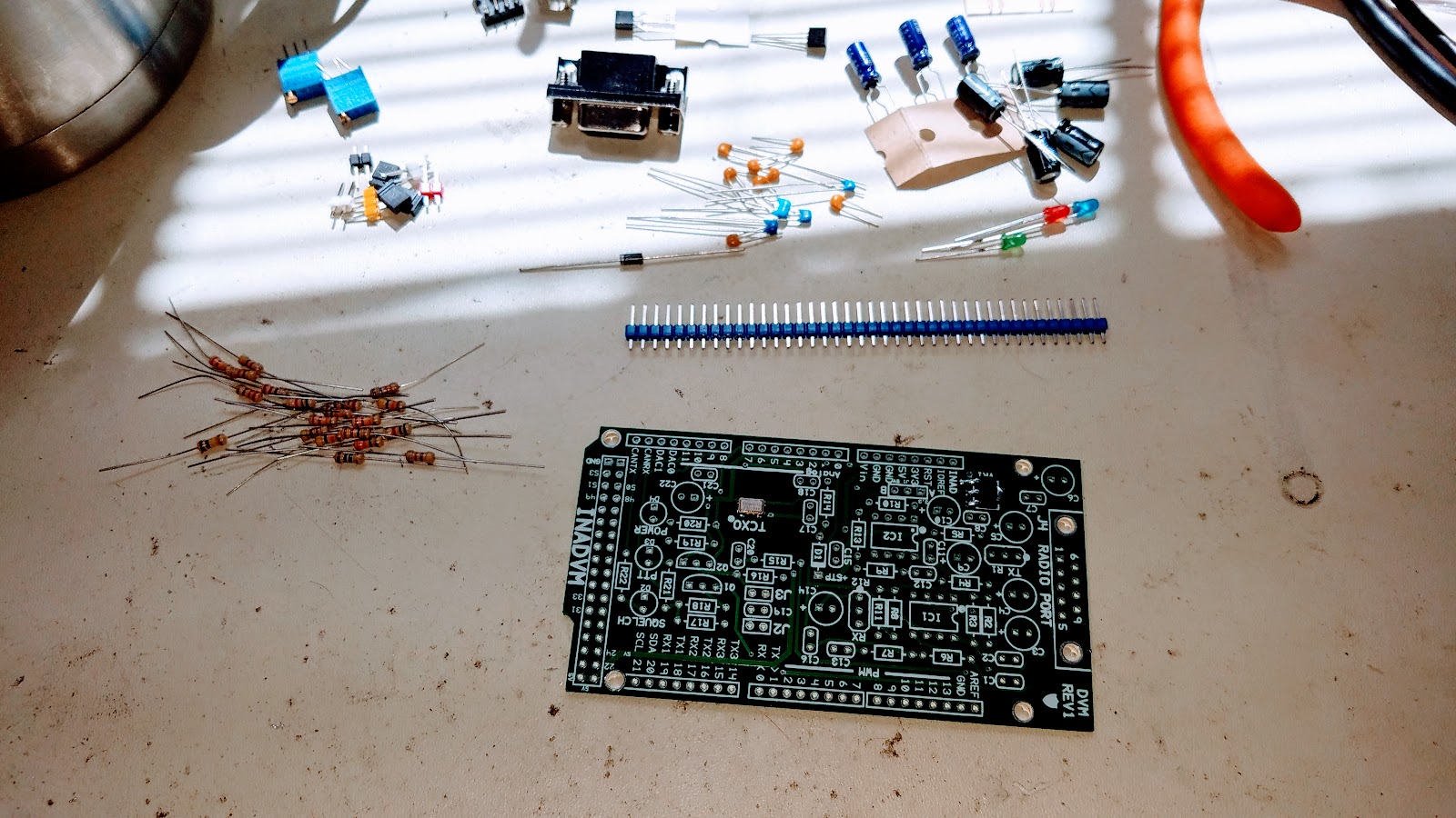
On a clean workbench assemble your tools. You'll need a 15W soldering iron, solder, the kit, your Arduino Due, test meter, chocolate cookies and a Brownian Motion Producer such as a nice hot cup of tea.


Dump out the contents of the anti static bag and inventory your kit per the parts list found here.


Conventional wisdom dictates that we build our kits in a particular order. This is usually mechanical, resistors, capacitors then finally semiconductors. We are NOT going to do that. We are going to build a stable platform for which to install all the parts. The platform will be made out of the electrolytic capacitors and other mechanical parts. This will help prevent the board from rocking whilst you are soldering on the other parts.

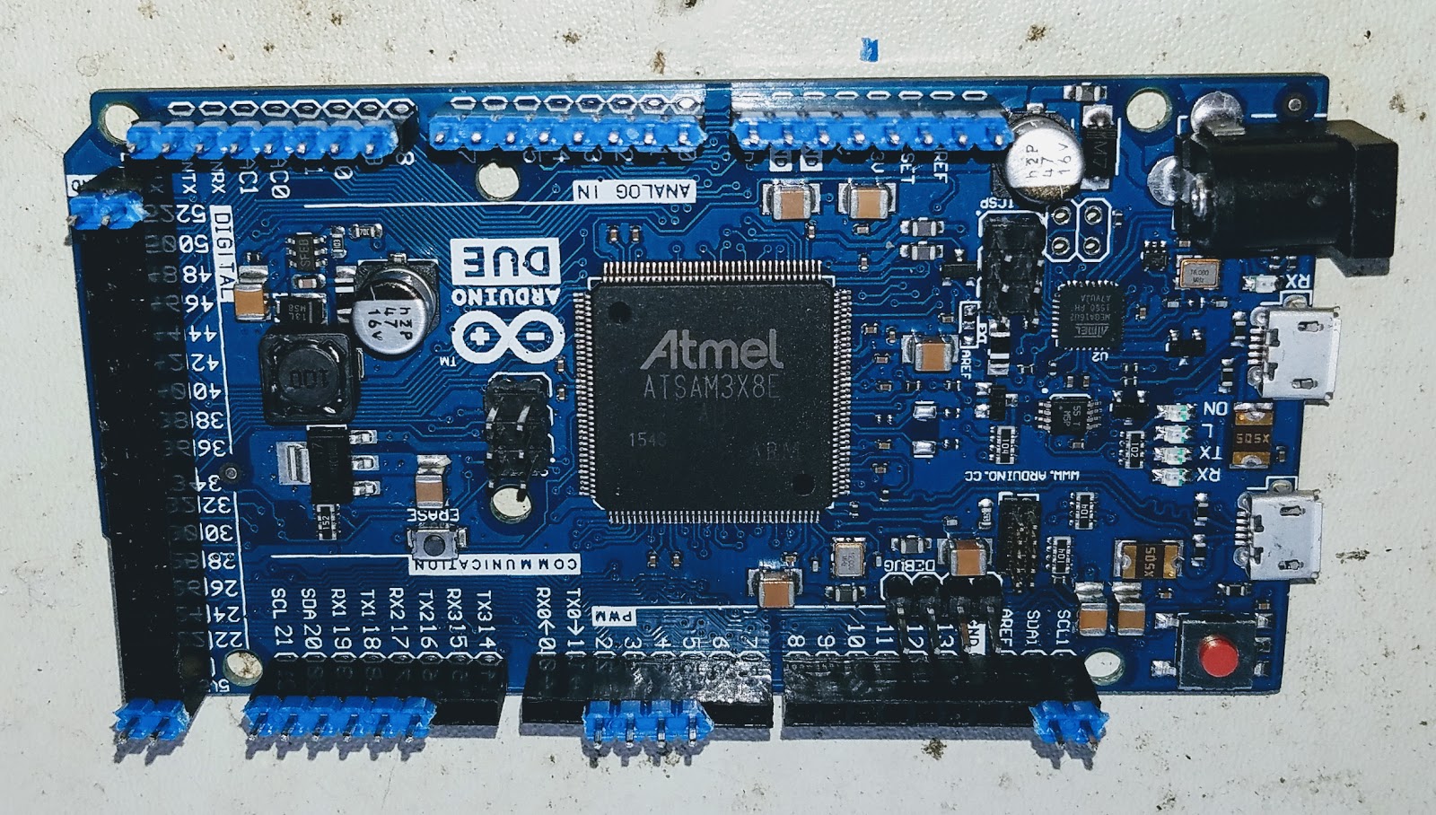
Install the header strip into the Arduino Due. This will greatly aid in aligning the headers when you mate the INADVM board. Make sure to install the long part of the header into the Arduino. The short part will go through the board and get soldered.


Place the board onto the Arduino and header pins. Solder only the pins that stick though the board.


You should end up with this when you complete this step.


Install all the electrolytic capacitors. Take care to orientate them correctly. The long leg goes to the "+" on the legend.


Now turn the board over and check for stability. Better, right?


Now it's time to take a well earned swig of your Brownian Motion Producer. Go ahead and treat yourself to one of those chocolate cookies too.

Install the rest of the mechanical parts. These are the IC sockets, DB9 connector, headers and jumpers. I also installed the variable resistors too. Pay attention to my orientation. The legend on the board is WRONG!! If you installed your part per the legend you'll be forced to adjust your modem in the reverse direction. Not a big deal but catch it now whilst you can. Install the jumper into position "A" on the yellow header.


Install the resistors, capacitors and the diodes. DO NOT install any of the transistor or IC parts! Install the board onto the Arduino and power it up. I connected my shack supply to the Arduino which can take up to 36V via the barrel connector.

Observe the board for blue smoke. If you see any disconnect the power IMMEDIATELY!  Using your meter check for 3.3V on pin 8 of both IC sockets. The "power" LED should also light up.


Unplug the board. Install the remaining parts paying attention to install the IC's the right way around.


That's it. You are now ready to install the firmware onto the Arduino and enjoy your modem. Go ahead and eat your last cookie. Heck! Get yourself a beer. You earned it!


Thursday 23 February 2017

Monday 13 February 2017

IoT gone mad

Spotted this in WalMart yesterday. It's a Wi-Fi enabled slow cooker. Yep. You heard me right. A Wi-Fi enabled slow cooker. It's got an app too!


The more I think about this the more I think it's a food poisoning outbreak waiting to happen. You dump your ingredients into the pot (see below for chili recipe) and then you leave the house for the rest of the day. Somewhere around lunchtime you connect to your slow cooker and turn it on for 6 hours. What's been going on with the raw meat that's been sitting in the pot all morning? I'll leave that to your imagination.

Hmmmnnnn ... I wonder what a hacker could do with access to your kitchen?


Ingredients

2lb lean (at least 80%) ground beef
1large onion, chopped (1 cup)
2cloves garlic, finely chopped
1can (28 oz) diced tomatoes, undrained
1can (16 oz) chili beans in sauce, undrained
1can (15 oz) tomato sauce
2tablespoons chili powder
1 1/2teaspoons ground cumin
1/2teaspoon salt
1/2teaspoon pepper

Directions
1 In 12-inch skillet, cook beef and onion over medium heat 8 to 10 minutes, stirring occasionally, until beef is brown; drain.
2 In 4- to 5-quart slow cooker, mix beef, onion and remaining ingredients.
3 Cover and cook on Low heat setting 6 to 8 hours.

Friday 10 February 2017

JNOS on Raspberry Pi

Inspired by the PiGate and already possessing the constituent parts (including the 3D printer to make the enclosure) I decided to try my hand at getting a JNOS system together. TCP/IP over radio fans will probably remember JNOS from way back when. Good news! It's still being maintained by Maiko Langelaar, VE4KLM http://www.langelaar.net/projects/jnos2/

As it turns out this project was quite trivial to put together. Maiko has done all the hard work with his software and John Hanson, W2FS did more hard work with his TNC-Pi hardware


The top 2 pictures show a RPi3 and a TNC-Pi housed in the PiGate 3D printed enclosure (should have printed it in OEM Orange!). The bottom picture shows the completed PiGate hardware connected to a KPC3+ via a direct audio cross-over cable.

So how do I build the JNOS? I started with a shiny new 8GB SD card that I picked up at Microcenter for $4 and a RPi3 which I also got from Microcenter for $30. I also downloaded the latest edition of Raspbian Jessie Lite. The Lite version does not have a GUI. Real men can use the Linux command line. /JFDI!! I'm not going to tell you how to install the RPi and get it onto your network. There are plenty of other resources available for that.

Before we start, have you confirmed that your TNC-Pi works correctly? You can use the tools from the TNC-Pi website to talk to the modem? You removed and added lines per the instruction on the website? Good.

Let us start by installing the the latest updates, patches and a few required libraries ...

sudo apt-get update
sudo apt-get upgrade
sudo apt-get install libssl-dev libncurses5-dev libncursesw5-dev

Now get the latest sources from Maiko's website and unpack it. Navigate to the 'src' directory. Copy the config.h.default file to config.h and edit it to your requirements.

Now for the hard part. Go ahead and 'make' JNOS. It'll take about 10 minutes so go and make a nice Brownian Motion producer.

So it's JNOS, right? So that means you'll need to craft all the relevant config and support files, autoexec.nos, ftpusers, rewrite, forward.bbs etc. But just to be nice I'll give you a head start on the modem config in autoexec.nos ...

#
# ---------- TNC-Pi specific----------
#
# We are using a single TNC-Pi KISS modem from Coastal Chipworks (hi John!!) configured to use the serial port @ 19200bps
attach asy ttyAMA0 - ax25 pitnc 1024 256 19200
# That's all. Carry on with the config
#
And that's really all there is to it. As stated previously I connected the RPi/TNC-Pi directly to my KPC3+ via a cross-over cable. I was able to connect to the JNOS BBS prompt as seen below. It just works.

Some links ...