Tuesday, 22 November 2016

Outernet Receiving System

Have you seen this? It's a free filecasting (one way file transmission) service that is delivered by satellite. "Satellite, you say? Sounds expensive." Not at all. And the skill level required to access this media source is also quite low.


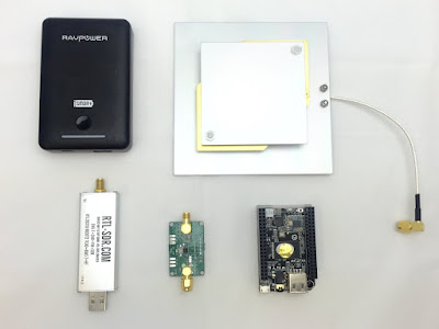
So what's this then? It's an L-band patch antenna for an Outernet receiving system. It is currently sitting just outside of my living room window looking up at the Inmarsat satellite at 98 degrees west.  

As you can see from this picture, the Outernet receiving system is little more than a USB based software defined radio. In my case it's plugged into a C.H.I.P. computer (similar to a RPi) which then makes the received files available via it's WiFi interface.


I bought the development/DIY kit from Outernet for $79. Mine did not come with the USB battery as I already had one of those.


Aligning the system was trivial. One of the advantages of the L-band (1.5GHz) is that as long as you have a clear sky you can "see" the satellite. You do not need to be aligned with the satellite as you would with a Ku (TV) band satellite. That said, if you can align the antenna you will increase the reliability of the data downlink. As you can see from the picture above, I got quite a good downlink from my window.


So far all I've received is a few Wikipedia pages and some weather maps etc. I also received the latest AMSAT keplarian elements too.

The system runs at 2400bd and so is very slow. But considering that its free I can live with it. The ultimate goal of Outernet is to launch 3 Cubesats which will circle the earth and have a faster downlink.

Tuesday, 18 October 2016

Ham radio install in a 2015 Chevy Sonic

My girlfriend has a Chevy Sonic. She also has a newly minted ham licence. And as if all that wasn't enough it was recently her birthday. She has a Yaesu FTM-100D. The job of installing it fell to me.

In a previous posting I installed the antennas onto her car.

On this outing we'll be installing the radio itself. The main body of the radio will reside in the cargo shelf at the back of the car whilst the control head, mic and speaker will be mounted in the front.

Let's get some power to the back of the car. Get yourself 15 feet of #12 or #10 black and red wire. Cut a hole in the large grommet in the firewall and pass the wire through it. It's easy to find right behind the battery. You can reach it from under the dashboard too.

Do not connect the wires to the battery just yet.


Now that your wire is pulled through from the engine bay, remove the covers from the drivers side door sills and feed the wire through to the back of the car. You will stop when you get to the back seat. Remove the flooring from the trunk to expose the spare wheel. Feed a cable snake from the trunk side of the seat to the drivers side door. Attach your cable and gently pull it back to the trunk. 


You may now replace the flooring in the trunk. I terminated the trunk end of the wire with 45Amp Anderson PowerPoles. In turn the cable will feed a fuse box for other equipment. Return to the engine bay and install a 30Amp fuse on BOTH the red and black wires then attach them to the battery. Test the wiring (you should have 12V at the trunk end of the cable). If all is well install the radio into the trunk.


Using the supplied remote head mounting kit, connect one end of the long black telephone style cable to the radio body and feed the other end under the rear seat, across the trans tunnel and into the drivers zone. Do the same with a remote speaker. The microphone will require you to obtain a 6P6C telephone cable. Make sure that it is wired 1-1 rather than 1-6 (reversed). I ended up buying a 25' cable from eBay and then cutting it to length before installing a new plug on the end. As you can see in the above picture, I fed all my control wires through a piece of cable dressing so as to keep them all together.


 Finally, using an RJ45 cable coupler, connect the mic to the mic cable. Also connect the head to the black control cable and position all items in your favoured position. I used 3M double sided tape to secure the head to a spot just below the radio control screen.

Don't forget to put your car back together again.

Monday, 10 October 2016

Never had one of these when I was in Dublin

I went out with a friend a few weeks back to an "Irish Pub". Staten Island is covered in "Irish Pub" establishments. The nearest any of them have been to Ireland is, well, they haven't.

It was with great humor that I read the menu of the place we went to. They offered a Dublin Works Burger". It's ingredients were listed below the title and are anything but Irish.


American and Pepper Jack cheese, Jalapenos, Thousand Island dressing along with the usual veggies all served on a Brioche bun. A classic Dublin Burger if never there was one.

2015 Chevy Sonic Antenna Install

I installed 3 antennas onto a 2015 Chevrolet Sonic this weekend. It was a simple install that will in turn be attached to some ham radio gear that is yet to be installed into that vehicle.

After discussion with the owner it was decided to install the main antenna supporting the voice radio into the middle of the roof. This will allow the optimal radiation pattern for the antenna. However, this would require removing the head liner from the vehicle to allow access to the center of the roof. A compromise was found by installing the antenna directly above the rear passenger dome light which was only slightly off-center to the vehicle.


The Dome light is easily removed by gently pulling on it. It will fall out and be held by it's supply cable. Remove the supply cable by pressing the clips found on either side of the connector. Remove the light and put it in a safe place for later restoration.

Now you are left with a rectangular space. Find the center of the space by drawing an X from the diagonally opposite corners of the hole. Drill a small pilot hole at the center of the X from the inside to the outside of the car.

Now drill out the hole you've made with increasingly larger drill bits until you have a hole that will correctly accept your antenna mount. My NMO mount required a 3/8ths hole but others require 1/2 inch or even 3/4 inch holes. Increasing the size of the hole in steps makes for a neater hole and reduces the risk of buckling the metal with the torque of the drill.

Clean up any shards and splinters with a slightly larger drill bit but be careful not to create a larger hole. Install the antenna mount into the hole you've made making sure to weather seal it where necessary.

Now we need to pull the coax from the mount into the back of the vehicle (the radio will be going into a pocket in the trunk). Feed a snake (I used a wire coat hanger) from the back of the car to the antenna mount, attach the coax to it and then gently pull it towards the back of the car.


Depending upon the style of the mount used you may have to insulate the bottom parts of the mount so as to prevent them shorting on the light. A strip of duct tape would be ideal for this. As you can see, my mount had a plastic cover already. Reconnect the dome light and reinstall it back into its hole. We are finished with this part of the installation.


I did say that I installed 3 antennas. For the remaining 2 I used a combined GPS antenna with NMO mount. This was installed at the back drivers side of the roof. I didn't get any pictures of the install as it started to rain just as I had drilled my pilot hole. But, here's the finished product ...


The flat part at the rear of the mount is the GPS antenna whilst the front part is an NMO mount. As you can see, the rain made taking pictures of the install impossible. 


Tuesday, 4 October 2016

Jamboree On The Air (JOTA) 2016

It's October already! Where has the summer gone?

If you've been around ham radio for a while you will have heard of the Jamboree On The Air (JOTA). It happens on the 3rd full weekend in October and is an opportunity for Scouts all over the world to get on the radio and chat with each other via ham radio.

 Do the clickey thing here


I've taken part in every JOTA event going back to 1988 and can honestly say that I've enjoyed every one of them. I was even involved in the startup of Jamboree On The Internet (JOTI) which is held concurrently over the same weekend.

If you've got a few spare minutes over the JOTA weekend please keep an ear out for the Scouts and drop in for a chat. It's an excellent opportunity for them to earn a few merit badges, discover ham radio and learn about peoples from all over the world.


I got this certificate from the now defunct International Listeners Association (hi, Trevor!!). Back in those days the UK Scouts had to receive 50 radio stations as part of their Communicator merit badge. Of course, they all complained that it was too hard so I sat down with them before breakfast on the Sunday morning and managed to log my required 50 in the time it took to get breakfast cooked (we were camping at the Scout hut).

Silliest Radio Award

I was on the radio a few days ago talking with the guys about radio awards. They were all bragging about their Worked All States and DXCC etc. When asked what "wallpaper" I had I was only able to reply that it took me almost 20 years to earn Worked All Continents. However, I do have a very exclusive award; the Worked All 31 Pierson Road Award. To my knowledge there are only 8 in existance.


Thursday, 16 June 2016

Raspberry Pi ST-4 compatible Autoguider

I'm working on a project to add a Raspberry Pi to my telescope setup. In the end it will do everything from plate solving to photography and also allow me to do it from the warmth of my armchair rather than standing out in the cold all night.

I'm not the first one to have thought of this and there are many ideas as to how to do it. Presented below is my take on an ST-4 compatible autoguiding interface. It plugs into the Pi's 40 pin I/O connector and sticks out of the case so as to allow the cable to connect from the guide port on your mount to the Pi. I've also added a DSLR trigger too.


I've uploaded the board to Oshpark so that you can order one (well, 3 really). The BOM is trivial and the opto chips are nothing special.

Order from OSH Park

Below are the Eagle files.

RPi_ST-4_Opto_Interface.brd
RPi_ST-4_Opto_Interface.sch

A bit of Group Therapy

I likes me a bit of Group Therapy every now and then.

Last night I did this at the local range. I rented a  Ruger American in 9mm and put the target out at 10 meters (a bit over 30 feet). As you can see, it did really well. I might have to get me one of those!


Wednesday, 18 May 2016

Yaesu FTM-100DR wideband TX modification

If you've been keeping up with my blog you'll know I have one of these radio's. So far it's been a great radio for the money (I got it on sale at HRO for less than $300). I need it to transmit on some none Ham frequencies and so need to modify it so that it will transmit out of the Ham bands. This modification is commonly knows as the "MARS/CAP mod".

There's nothing new under the sun and certainly not on the Internet so that's where I went looking first. A Google search led me this document which outlines the modifications for both the FTM-400 and FTM-100 radio's. It's wrong!!!!

Or rather, it's not quite correct. Whilst the document correctly outlines the modification procedure for the FTM-400 it only outlines the procedure for the European version of the FTM-100DR. It's all about removing the resistors y'see. Using the pictures in the above document I noticed that the EU resistor was already removed in my radio. Erm ..... WTF? So it does appear that the modifications for the 400 are the same as for the 100.

Original picture from here

Take the top cover off your radio and orient it with the mic socket facing you. In the bottom left will be a white sticker with a slot in it for the firmware upgrades. Carefully remove the sticker to reveal the backup battery and a screw as above.

If you have an EU version the resistor that would be removed for the US version is already missing. The same is true in reverse for the US version. In short, you will remove the relevant resistor so that in the end you will have no resistors in either the EU or US position. My US version already had the EU resistor removed so all I had to do was remove the US resistor.

Click on the above picture for a better look at what to remove. The usual caveats apply; I won't be held responsible for your bad soldering work. If your car explodes when you key up on your local CAP repeater that's your lookout.

The radio will reset itself when you first power it on. You'll need to make sure that either you back it up before carrying out the mod or somehow reprogram the radio when you turn it back on again. This part is still causing me issues but that's another story.

###### UPDATE 20160518 ######

Reprogramming the newly modified radio is a bit of a nightmare. All of your saved memory files will no longer work. I tried to restore the radio memories etc from the backup I had made to its SD card but the radio displayed an error whenever I did it.

The fix was to move the SD card to the laptop running the programming software. I read the SD card into the software then saved it as a CSV file. Returning the SD card to the radio I formatted it and then performed a backup to the SD card.

I then returned the SD card to the laptop and read card in again. Now that I had an active file I "Inport" (there's lots of spelling mistakes in the Yaesu software) the CSV file and then send all the data back to the SD card. Finally I moved the SD card back to the radio and read in the memory information. The radio rebooted when it was done reading the file and there were all my memory channels restored.

Why didn't I use the programming cable? This is gonna sound silly but you need 2 people to do this when you remote mount the radio. I couldn't set the radio to clone mode and then run to the trunk to press the buttons on the laptop before the radio timed out. I'm sure this would have been a less painful way to reprogram the radio. Maybe next time I'll enlist some help?

Amateur Astronomer of the Year


This was an unexpected surprise. Was at the Society's dinner last night and walked away with this.

Tuesday, 19 April 2016

Yaesu FTM-100DR GPS issues

Having wrestled with my new car to install my ham radio gear into it I discovered this problem. I bought a Yaesu FTM-100DR Digital Fusion radio for my car. Let's not bother with with what it does or how D-STAR or DMR may or may not be better than Fusion.

It has a built in GPS receiver. It uses the information from this receiver to tag the digital voice packets with my current position. Except that it doesn't. Or rather it doesn't do it correctly. It does tag my outing data with an GPS position; just not my actual position. Take a look at the below picture.


Where is the radio? According to Google and other mapping sites my car is in the middle of nowhere on the side of a mountain in Western China not too far from the borders with Pakistan in the South and Tajikistan in the West.

Yes, the software that's interpreting the GPS data is clearly having an issue. I can indeed confirm that this picture was taken in Wilmington, Delaware. Examination of the GPS metadata in the picture will confirm this.

I've not been able to confirm what this .... erm .... "undocumented feature" .... has affected within the data stream itself. Is it merely a cosmetic GUI issue? Am I actually telling the world that I'm in China? Am I sending any position data at all? An examination of my station details as forwarded to the greater Yaesu Fusion network would reveal the answers. However, none of my local Fusion repeaters are connected to the Internet.

One of the features of this radio is that it has APRS abilities. It can transmit my location to the APRS network via it's built in GPS, AX.25 modem and of course, the radio. So that's what I did next. With help from Charlie, N2NOV I configured the radio as an APRS tracker with the callsign NI2O-2. I then went for a long drive. You can see my journey here.

As you can see, I took a drive East along I80, Rt46 and Rt3. Then South East along the NJ Turnpike to Delaware. Charlie would check my progress every now and then to see how I was making out. In parallel to the Yaesu I was also running my $100 APRS Tracker Mk2 and also APRSDroid, an APRS app on my cellphone.

The fact that you can follow me in the USA rather than Western China tells me that the GPS issue is a cosmetic one. It would seem that the positioning data tagged to the APRS is correct. I have discovered 3 firmware updates for this radio so I expect that this issue has been addressed but unfortunately none of the firmware update files comes with a "fix list" so it is unknown as to what issues have been addressed.

###### UPDATE 20160423 ######

So I downloaded the firmware updates and set about installing them. I installed them one by one per the instructions from the Yaesu website and then did a "factory reset" also per the instructions. It turns out that the "panel" firmware update was the one at fault. Unfortunately there were no revision notes with the firmware updates so that one may know what the resolved issued may have been but at least we know now that one of them was the E/W display error.

So far it seems to be working very well. If only I could use CHiRP to program it I'd be a happy boy.

Thursday, 7 April 2016

Ham radio install in a 2015 Nissan Rogue

I bought a new car recently. It's taken me over a month to work out how to install my ham radio gear into it. Finally I discovered a few websites and chat forums where guys were installing high end stereo equipment into their vehicles. I got much advice from them. The below details my adventures.

All my radio's can be remote mounted. This means that the actual radio can be separated from the control head by means of a control cable. I've taken to installing my radio's in the back of the car with the control heads on the dashboard.

Far at the back of the car in the trunk area is an access panel that leads to the spare wheel. There's also a tray that runs the width of the car. It's just deep enough to place all my radio gear into.


So now that the radio's are secured how do they get connected to the control heads in the front of the vehicle? That had me stumped for a while. Then I noticed these wires arriving from the back seat side of the car. Look closely and you'll see them either side of the hinge straps that hold the trunk floor in place. Where do they come from?


I was able to remove the seat cushion from the back seat. It's held on by just 2 clips. Can you see that cable loom at the bottom that vanishes under the seat back cushion?


Back to the spare wheel well. Remove the wheel jack and tools from the bin they are in and you'll see a square hole. In the hole is another cable loom. Remove the 3 Philips head screws that hold the tool bin in place to reveal the whole loom. It goes to the rear light cluster.


I inserted a cable fish into the gap that the cable loom used to get from the back seat to the trunk. I attached all my various wires (power, control, microphone, speaker and some spares) and pulled them all through from the trunk to the back seat. Carefully remove the plastic strip that's right at the door threshold to reveal another cable loom. The loom goes along the door sill, past the seat belt anchor and into the front. Remove the front door cover to expose more loom. I used the existing cable anchors to hold my new cables.


Having pulled all my cables from the back to the front I put the back seat and trunk back together again. The cables will be fed into the dashboard and installed into the control heads, microphones and speakers. Power also needs to be connected to the battery so a path through the firewall is required.

The usual way through a firewall is to find the vehicle's cable loom and piggy-back through the same hole. Good luck with that!! An inspection of the underside of the dashboard does not reveal any obvious candidates and neither does the engine bay. I was able to trace the engine hood release cable to the driver's side of the firewall but could not find it on the engine side. That's when I went back to the Nissan chat forum. Turns out that you have to remove the wheel and the fairing!!!


A closer look inside the wheel arch, behind the fairing reveals some useful grommets and even a spare one! Woohoo!! Where's my cable fish?


So now I had to find a tidy path from the cable tunnel along the door sill, up underneath the dashboard and out of the hole I found. Removing the plastic panel next to the door revealed a huge loom. I followed it and it led me to the hole I'm going to use.  Incidentally, the heavy duty red and blue wires in the picture are switched 12V and constant 12V from the car battery going to and from the ignition. You could tap in there if you wanted a switched source. Max current is 40 Amps as dictated by a fuse at the battery terminal.


So with my cable fish (is it a fish or a snake? I have always heard it that you snake a cable with a fish?) inserted through my hole from the wheel arch side, I pulled the power cables through to the engine side. Then I found a path from the wheel to the engine and popped out right by the battery.


 Connection to the battery was made with two fused 30 Amp pigtails; one fuse for the positive battery terminal and the other for the negative battery terminal. I also connected the engine block to the battery directly as well as the body work to the battery directly. All connections were made with #10 wire and waterproof crimp-n-shrink connectors.
 

Wednesday, 23 March 2016

$100 APRS Tracker Mk2

Way back (2001) before they invented Internet 2.0 I built an APRS tracker for less than $100. It was a collection of stuff slapped together into a box and sported a TinyTrak tracker, GPS receiver and a 2 watt transmitter. In its day it was quite an achievement. Most APRS implementations would run over $150 and require an old TNC and a full FM transceiver. GPS's in those days were also big and ugly too. To this day I still get requests for the radio I used.

Well, over the years it has had updates and repairs and even had a 10W linear amplifier added to improve its range but yet it was still a pile of components slapped together into a somewhat large box. It finally gave up the ghost and forced me to go a different route. I briefly looked at creating my own tracker but abandoned it due to time constraints and other projects.

That was then. This is now. I bought a new car recently and am in the throws of moving my radio gear into it. Whilst I have a "black box" radio that will do APRS very well I still want to run my own bespoke APRS tracker. So that led me back to the $100 APRS Tracker.

Looking around the shack I found an old Motorola SM50 left over from a D-STAR HotSpot project. All I needed now was the tracker and a GPS receiver. Then I remembered that I had looked at this project a few years back. At that time I was playing with Ublox NEO-6 GPS modules for use in NTP time servers. These are sub $10 GPS receivers for adding to your projects. They are trivial to use requiring just 3.3v and an antenna. As you can see from the below picture I was able to integrate one into a tracker prototype (it's that white square blob).


But it didn't work. Or rather, it worked badly. Whilst it would talk to the config software when attached to the PC and indeed would send a beacon it wouldn't send any position data. Now I remember why I abandoned it. Having a little more time now I took another look. 

Turns out that the problem was trivial. In its old form (pictured above) the GPS was spitting out position data at 9600bd but the PIC microcontroller was expecting the data at 4800bd. DUH!! The fix was to ground one of the config pins on the GPS thus forcing it into 4800bd mode. In writing this page and getting the files etc together I've come across some auto detecting firmware that makes this problem go away. And I can tell you that it works wonderfully! If only I had bothered to look a little harder the first time around.

So let's do some accounting ...
  • Motorola SM50 FM transceiver    $30  ebay
  • Tracker PCB                                  $8    oshpark.com
  • Ublox NEO-6 GPS RX module     $12  ebay
  • PIC 16F628 microcontroller          $3    ebay
  • SMA antenna connector                 $1    hamfest
  • Motorola pre-wired 16 pin plug     $4    ebay
  • GPS "hockey puck" antenna          $5     ebay
  • 1/4 wave 2 meter antenna               $8    ebay
  • Mag mount for 2M antenna            $14  ebay
That's a grand total of $85. And if you already have some spare 2M antennas kicking around you can shave another $22 of that for a potential $63.

So I've parked all the board stuff on oshpark.com for you to order. You'll get 3 boards for $22. The PCB will allow you to use any current Ublox NEO-x GPS modules. They'll spit out 9600bd data so you'll have to use 9600bd compatible PIC APRS code. Luckily I've linked to that below. You can also change the PIC for a slightly better one which will have more facilities. 


Order from OSH Park

Eagle files for download ...


PIC microcontroller code for download ...

kf163tracker-2.0.2.iso It's a bootable Linux disk. Contains firmware, manuals and config software.

Thanks to DK7IN for his original idea and PE1ICQ for his expansion of this idea and his excellent code.

Monday, 11 January 2016

Adventures in IPTV

I do a bit of network consultancy here and there. One of my clients is a mom-n-pop cable TV operator whom wants to convert his plant from analog to digital. It's about time. The digital switchover was 10 years ago!!

Anyway, having sorted him out and converted his 80 or so analog channels back to digital (they are derived from a satellite TV network that transmits in H.264) it was a simple matter of bundling the TV stations into the correct size of RF mux and transmitting that mux over the cable network.

A happy side effect of this project is that I acquired a UT-100C USB DVB-T modulator dongle which is becoming increasingly popular in the amateur TV world. More about that another time.

To test my work I compiled a list of some IPTV channels currently (at time of writing) available over the internet. I forwarded the sources to an instance of OpenCaster which was handling the actual RF broadcast part and then connected the USB TX to a 100ft roll of TV coax.

The far end of the coax was connected to an El-Tigre DVB-C/IPTV set top box which I got from ebay for $25 new. As if by magic some pictures appeared on the attached TV.

So where does the IPTV come in? The "inner workings" of your local cable company is all IP today. TV sources are moved around the data network in IP format and in many cases derived from the original broadcaster as IPTV also. Eventually these sources are combined into some sort of data mux and then converted to RF for onward transmission to your TV.

I splashed out an bought myself a new 55" LG smart TV too. One of the applications one can download from LG's store is an IPTV client. I was not only able to test the feed I was making for my client directly onto a TV but also to load up the below playlist into it. I can now get some 28 channels over the Internet directly to my TV.

Cut and paste the below text into a file and then load it into your favourite media player or set top box.

group,Music
ext,Vevo1 HD,http://vevoplaylist-live.hls.adaptive.level3.net/vevo/ch1/05/prog_index.m3u8
ext,Vevo2 HD,http://vevoplaylist-live.hls.adaptive.level3.net/vevo/ch2/05/prog_index.m3u8
ext,Vevo3 HD Country,http://vevoplaylist-live.hls.adaptive.level3.net/vevo/ch3/05/prog_index.m3u8
1hdru,1HD,http://109.239.142.62:1935/live/livestream3/playlist.m3u8
ext,NOW Music,http://ngx.cr1.streamzilla.xlcdn.com/session/3e871f51e3dbe7ed88a5a044197ba590/sz/AATW/wowza4/live/nowmusic/chunklist.m3u8

group,Sports
ext,Sports Night HD,rtmp://freeview.fms.visionip.tv/live/sports_tonight-sports_tonight-live-25f-16x9-HD
ext,Xtreme Impacts,http://46.249.213.93/iPhone/broadcast/xtremeimpacts-tablet.3gp/xtremeimpacts-tablet.3gp-mr647k.m3u8
ext,Antena 3 Sports HD,http://antena3-aos1-apple-live.adaptive.level3.net/apple/antena3/channel01/antena_3_hd_1548K_1280x720_main.m3u8
ext,Big Ten HD,http://bigten247.cdnak.bigtenhd.neulion.com/nlds/btn2go/btnnetwork/as/live/btnnetwork_hd_3000.m3u8
ext,NBCSN,http://tvenbcsn-i.Akamaihd.net/hls/live/218235/nbcsnx/4296k/prog.m3u8
ext,PAC National,http://xrxs.net/video/live-p12netw-2328.m3u8
esp,Eurosport,http://37.220.21.210:57088/hbird/sdtv/planet/Eurosport

group,News
bbc-world,BBC World News,http://wpc.c1a9.edgecastcdn.net/hls-live/20C1A9/bbc_world/ls_satlink/b_828.m3u8
ext,CNBC,http://wpc.c1a9.edgecastcdn.net/hls-live/20C1A9/cnbc_eu/ls_satlink/b_,264,528,828,.m3u8
ext,ABC News,http://abclive.abcnews.com/i/abc_live4@136330/index_1200_av-b.m3u8
cnn,CNN USA,http://wpc.c1a9.edgecastcdn.net/hls-live/20C1A9/cnn/ls_satlink/b_828.m3u8
bloomberg,Bloomberg,http://cdn3.videos.bloomberg.com/btv/us/master.m3u8?b
ext,RT America,http://odna.octoshape.net/f3f5m2v4/cds/ch4_720p/chunklist.m3u8
rt-doc,RT Documentary HD,http://odna.octoshape.net/f3f5m2v4/cds/ch5_720p/chunklist.m3u8
ext,Sky News International,http://wpc.C1A9.edgecastcdn.net/hls-live/20C1A9/skynews/ls_satlink/b_,828,528,264,.m3u8
ext,AL JAZEERA,http://wpc.c1a9.edgecastcdn.net/hls-live/20C1A9/aljazeera_en/ls_satlink/b_528.m3u8
france24,France 24,http://wpc.C1A9.edgecastcdn.net/hls-live/20C1A9/france24_en/ls_satlink/b_,828,528,264,.m3u8

group,Shopping
ext,HSN,rtmp://hsn.mpl.miisolutions.net:1935/hsn-live01/_definst_/mp4:420p500kB31?b?b*t$ playpath=mp4:420p500kB31
ext,HSN 2,rtmp://hsn.mpl.miisolutions.net:1935/hsn-live01/_definst_/mp4:468p500kB31?b?b*t$ playpath=mp4:468p500kB31
ext,JewelryTV,rtmp://jtvmedia.jtv.com:1975/live/live6

group,Other
ext,London Live,http://bcoveliveios-i.akamaihd.net/hls/live/217434/3083279840001/master_900.m3u8
ext,Cartoon work,http://54.255.155.24:1935//Live/_definst_/sweetbcha1novD28_W_150.sdp/playlist.m3u8

group,Test
ext,NTSC 4x3 Test,http://devimages.apple.com/iphone/samples/bipbop/bipbopall.m3u8

Bond, James Bond ...

I've recently taken up shooting. In keeping with this new hobby I've also started a growing pile of arms.

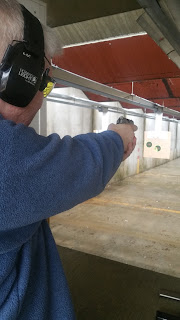
Whilst at the range on Sunday morning I noticed one of my range buddies shooting a .380 caliber pistol. It turned out to be a Walther PPK. Yep, the one that James Bond uses. Well, I had to try it. For a spy trying to conceal a weapon this might be the ideal gun. However, for a weapon of assassination, not so much. I could barely hold it in my hand. That's me in the picture below. My hands are bigger than the gun. I did manage to put all 8 rounds into the bullseye on the target at 10 yards.


I'm itching to try a Sig P226. The one that Bond shows his girlfriend in the latest "Spectre" movie. I thought it odd that Bond would have that in his pocket but rumour has it that the SAS and the MOD use it so I guess it wouldn't be too far fetched. Of course, it could have been a product placement too?