Here in the DE/MD/NJ/NY/PA area of the US we have a supermarket chain called ACME. I swear to Bob that it is run by idiots!
I spotted this in my local store recently.
It's a recall notice. It tells of a product recall for a chicken nugget food item. But look behind it on the shelf (click the pic to enlarge). It's the very same item that has been recalled!!!!
Saturday, 29 July 2017
Tuesday, 25 July 2017
3D printed Anderson Powerpole distribution box
I have a Robo3D 3D printer which I'm having a lot of fun with. I'm also trying to build a GMRS repeater for use on a farm. I laid out all the hardware only to discover that I needed a tidy way to distribute the power to the various devices.
Meet the Parametric PowerPole Breakout Box which can be found here on Thingiverse. The Parametric part comes from the way in which you can create anything from a 2 port to an 8 port box.
That is #12 solid electric wire connecting the PowerPoles together. I pulled the ground wire from a small run of Romex household electrical wire and used it to connect things together. The joins were wrapped and soldered and the ends were crimped and soldered.
Depending where you get them from PowerPoles can be as much as $2 a pair so using that price as a guide (I buy mine in bulk and have them on hand) I managed to construct this box for about $15 including the price of the PLA 3D printer material, electricity etc. Not too shabby!!
![]() |
| The repeater being laid out on a 2'x2' piece of 3/4 plywood |
I printed a 4 port box. As you can see, it has 6 ports. No my printer did not do it wrong. The ports at either end allow the power to be connected to the box without loosing one of the 4 ports. One can also stack the box together to make larger boxes. In the above pictures I've assembled the connectors the wrong way - DOH. Luckily I caught it before I soldered it all together.
Depending where you get them from PowerPoles can be as much as $2 a pair so using that price as a guide (I buy mine in bulk and have them on hand) I managed to construct this box for about $15 including the price of the PLA 3D printer material, electricity etc. Not too shabby!!
Schrodinger's Cats?
What is it about cats and boxes. Every time you put an empty box down onto the floor it becomes immediately inhabited by a cat. Or does it? 😉 Perhaps this was what captured Schrodinger's imagination and shaped his ideas on Quantum Physics?
For the cat lovers out there, here is a collection of just a few of the cats that inhabit my apartment. Please understand that they are not _my_ cats. Indeed, one of the cats has another cat as his pet.
![]() |
| Elvis |
![]() |
| Gracie |
![]() |
| Boots AKA Orange Dog |
![]() |
| Gracie |
![]() |
| For his next trick, Boots will make a girl disappear |
![]() |
| Rascal. He's a Lhasa Apso with a Doberman complex. The cats are bigger than him. |
Wash my clothes in what?
Found at the local Korean supermarket
My girlfriend asked if they had any Dragon dung but this was the closest they had.
Wednesday, 14 June 2017
Programming the Motorola SM50 under Linux
The Motorola SM50 and SM120 are quite a common radio and pop up on eBay all the time for modest prices. As with all Moto gear they come in a variety of models; wideband, narrowband, 2 channel, 16 channel, 40 watt, 4 watt etc etc etc. There are various model decoders available around Al Gore's Interweb Tubes so we won't be covering that here.
I am the proud owner of quite a pile of SM120 M44DGC20C2AA (40W UHF high wideband) models which are ideal for a repeater blabber box, GMRS or FirstResponder use such as your local Ambulance Squad.
Programming them back in the early 90's (yep, they are even older than that!) was by way of a DOS program running on a lowly i286 PC. But hold on, we are on Linux. How's that gonna work? Take a quick look at this youtube video ...
Things you'll need:
A Linux box (DUH!)
DosBox emulator software (apt-get install dosbox)
SM50 programming software (can't help you there but it's not hard to find)
Motorola GM300 style programming cable or "RIB" (I use a USB one from ebay)
How to do it:
Using your favourite terminal program (I use Yakuake) fire up the dosbox emulator by typing 'dosbox'. If you have a Z: prompt then that part works.
Unpack your SM50 software into a folder. Navigate to that folder and then fire up your favourite text editor. we'll be making a config file called 'sm50dosbox.conf'. Mine looks like this ...
[cpu]
core=auto
cputype=auto
cycles=191
cycleup=10
cycledown=20
[serial]
serial1=directserial realport:ttyUSB0
serial2=dummy
serial3=disabled
serial4=disabled
[dos]
xms=true
ems=true
umb=true
keyboardlayout=auto
[autoexec]
# Lines in this section will be run at startup.
# You can put your MOUNT lines here.
mount C /home/g7ltt/raid/Filestore/DOS
mount M /home/g7ltt/raid/Filestore/motocd/SM50/R030000
m:
m:\SM50.EXE
Adjust the 'serial' lines to match your USB port. Also adjust the 'mount' lines to reflect your path. In my case 'C' becomes C: and holds a few DOS utilities. The 'M' becomes M: which contains my SM50 software.
Save your file and the type 'dosbox -conf sm50dosbox.conf' and watch it all fire up. You'll have to configure the dos software to use COM1 but otherwise you'll be programming in no time.
In theory this should work for other Motorola DOS based programming tools for other radio's. However, I've not been able to get the GM300 or Maxtrac software to communicate with the radio. It seems that (for USB cables at least) the serial speed of 930bps is not supported by either the OS or the emulator.
If you get one of the other DOS programs to work please do drop me a line.
In theory this should work for other Motorola DOS based programming tools for other radio's. However, I've not been able to get the GM300 or Maxtrac software to communicate with the radio. It seems that (for USB cables at least) the serial speed of 930bps is not supported by either the OS or the emulator.
If you get one of the other DOS programs to work please do drop me a line.
Tuesday, 9 May 2017
Selfies; 1890's style
I went to the Delaware Museum of Art this past weekend. Of all the works installed there I found nothing of interest until I saw this sculpture.
That's a bunch of grapes she's holding in her right hand. It occurred to me that I've seen this pose before. It's the selfie pose. Raise the phone high into the air and then snap a picture of yourself whilst making a duck like face.
Being able to reach up to the hand with the grapes I obliged the woman.
Tuesday, 2 May 2017
INADVM Rev1 build
I bought this http://inadvm.com/inadvm/inadvm-index.html Its a multi mode modem for use with Fusion, DMR and D-STAR radio systems. One uses it with MMDVM software to create a multi mode hotspot.
The board I bought is a development board. It is already in Rev2 but much of the board is the same. The difference between the revisions is simply RSSI facilities added to Rev2.
There being currently no construction and test details I documented my construction and initital testing of the modem.
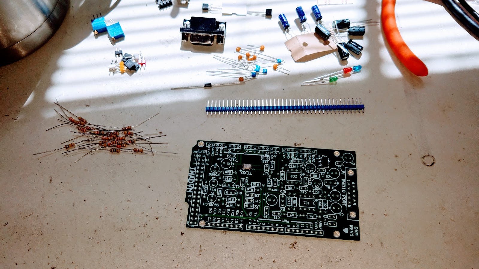
On a clean workbench assemble your tools. You'll need a 15W soldering iron, solder, the kit, your Arduino Due, test meter, chocolate cookies and a Brownian Motion Producer such as a nice hot cup of tea.
You should end up with this when you complete this step.
Now turn the board over and check for stability. Better, right?
The board I bought is a development board. It is already in Rev2 but much of the board is the same. The difference between the revisions is simply RSSI facilities added to Rev2.
There being currently no construction and test details I documented my construction and initital testing of the modem.
On a clean workbench assemble your tools. You'll need a 15W soldering iron, solder, the kit, your Arduino Due, test meter, chocolate cookies and a Brownian Motion Producer such as a nice hot cup of tea.
Dump out the contents of the anti static bag and inventory your kit per the parts list found here.
Conventional wisdom dictates that we build our kits in a particular order. This is usually mechanical, resistors, capacitors then finally semiconductors. We are NOT going to do that. We are going to build a stable platform for which to install all the parts. The platform will be made out of the electrolytic capacitors and other mechanical parts. This will help prevent the board from rocking whilst you are soldering on the other parts.
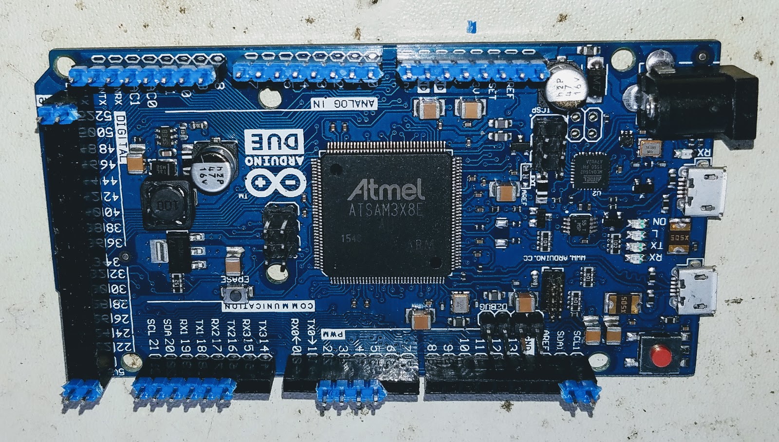
Install the header strip into the Arduino Due. This will greatly aid in aligning the headers when you mate the INADVM board. Make sure to install the long part of the header into the Arduino. The short part will go through the board and get soldered.
Place the board onto the Arduino and header pins. Solder only the pins that stick though the board.
Install all the electrolytic capacitors. Take care to orientate them correctly. The long leg goes to the "+" on the legend.
Now it's time to take a well earned swig of your Brownian Motion Producer. Go ahead and treat yourself to one of those chocolate cookies too.
Install the rest of the mechanical parts. These are the IC sockets, DB9 connector, headers and jumpers. I also installed the variable resistors too. Pay attention to my orientation. The legend on the board is WRONG!! If you installed your part per the legend you'll be forced to adjust your modem in the reverse direction. Not a big deal but catch it now whilst you can. Install the jumper into position "A" on the yellow header.
Install the resistors, capacitors and the diodes. DO NOT install any of the transistor or IC parts! Install the board onto the Arduino and power it up. I connected my shack supply to the Arduino which can take up to 36V via the barrel connector.
Observe the board for blue smoke. If you see any disconnect the power IMMEDIATELY! Using your meter check for 3.3V on pin 8 of both IC sockets. The "power" LED should also light up.
Unplug the board. Install the remaining parts paying attention to install the IC's the right way around.
That's it. You are now ready to install the firmware onto the Arduino and enjoy your modem. Go ahead and eat your last cookie. Heck! Get yourself a beer. You earned it!
Subscribe to:
Posts (Atom)