I bought this
http://inadvm.com/inadvm/inadvm-index.html Its a multi mode modem for use with Fusion, DMR and D-STAR radio systems. One uses it with
MMDVM software to create a multi mode hotspot.
The board I bought is a development board. It is already in Rev2 but much of the board is the same. The difference between the revisions is simply RSSI facilities added to Rev2.
There being currently no construction and test details I documented my construction and initital testing of the modem.
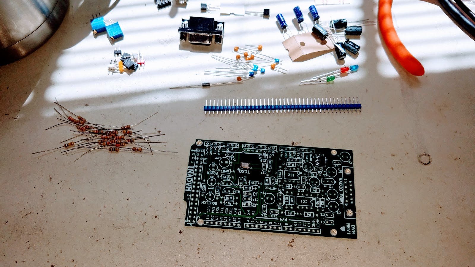
On a clean workbench assemble your tools. You'll need a 15W soldering iron, solder, the kit, your Arduino Due, test meter, chocolate cookies and a Brownian Motion Producer such as a nice hot cup of tea.
Dump out the contents of the anti static bag and inventory your kit per the parts list found
here.
Conventional wisdom dictates that we build our kits in a particular order. This is usually mechanical, resistors, capacitors then finally semiconductors. We are NOT going to do that. We are going to build a stable platform for which to install all the parts. The platform will be made out of the electrolytic capacitors and other mechanical parts. This will help prevent the board from rocking whilst you are soldering on the other parts.
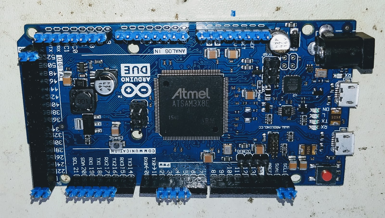
Install the header strip into the Arduino Due. This will greatly aid in aligning the headers when you mate the INADVM board. Make sure to install the long part of the header into the Arduino. The short part will go through the board and get soldered.
Place the board onto the Arduino and header pins. Solder only the pins that stick though the board.
You should end up with this when you complete this step.
Install all the electrolytic capacitors. Take care to orientate them correctly. The long leg goes to the "+" on the legend.
Now turn the board over and check for stability. Better, right?
Now it's time to take a well earned swig of your Brownian Motion Producer. Go ahead and treat yourself to one of those chocolate cookies too.
Install the rest of the mechanical parts. These are the IC sockets, DB9 connector, headers and jumpers. I also installed the variable resistors too. Pay attention to my orientation. The legend on the board is WRONG!! If you installed your part per the legend you'll be forced to adjust your modem in the reverse direction. Not a big deal but catch it now whilst you can. Install the jumper into position "A" on the yellow header.
Install the resistors, capacitors and the diodes. DO NOT install any of the transistor or IC parts! Install the board onto the Arduino and power it up. I connected my shack supply to the Arduino which can take up to 36V via the barrel connector.
Observe the board for blue smoke. If you see any disconnect the power IMMEDIATELY! Using your meter check for 3.3V on pin 8 of both IC sockets. The "power" LED should also light up.
Unplug the board. Install the remaining parts paying attention to install the IC's the right way around.
That's it. You are now ready to install the firmware onto the Arduino and enjoy your modem. Go ahead and eat your last cookie. Heck! Get yourself a beer. You earned it!