Showing posts with label APRS. Show all posts

Wednesday, 14 June 2017

Programming the Motorola SM50 under Linux

The Motorola SM50 and SM120 are quite a common radio and pop up on eBay all the time for modest prices. As with all Moto gear they come in a variety of models; wideband, narrowband, 2 channel, 16 channel, 40 watt, 4 watt etc etc etc. There are various model decoders available around Al Gore's Interweb Tubes so we won't be covering that here.

I am the proud owner of quite a pile of SM120 M44DGC20C2AA (40W UHF high wideband) models which are ideal for a repeater blabber box, GMRS or FirstResponder use such as your local Ambulance Squad.

Programming them back in the early 90's (yep, they are even older than that!) was by way of a DOS program running on a lowly i286 PC. But hold on, we are on Linux. How's that gonna work? Take a quick look at this youtube video ...


Things you'll need:

A Linux box (DUH!)
DosBox emulator software (apt-get install dosbox)
SM50 programming software (can't help you there but it's not hard to find)
Motorola GM300 style programming cable or "RIB" (I use a USB one from ebay)

How to do it:

Using your favourite terminal program (I use Yakuake) fire up the dosbox emulator by typing 'dosbox'. If you have a Z: prompt then that part works.

Unpack your SM50 software into a folder. Navigate to that folder and then fire up your favourite text editor. we'll be making a config file called 'sm50dosbox.conf'. Mine looks like this ...

[cpu]
core=auto
cputype=auto
cycles=191
cycleup=10
cycledown=20
[serial]
serial1=directserial realport:ttyUSB0
serial2=dummy
serial3=disabled
serial4=disabled
[dos]
xms=true
ems=true
umb=true
keyboardlayout=auto
[autoexec]
# Lines in this section will be run at startup.
# You can put your MOUNT lines here.
mount C /home/g7ltt/raid/Filestore/DOS
mount M /home/g7ltt/raid/Filestore/motocd/SM50/R030000
m:
m:\SM50.EXE
Adjust the 'serial' lines to match your USB port. Also adjust the 'mount' lines to reflect your path. In my case 'C' becomes C: and holds a few DOS utilities. The 'M' becomes M: which contains my SM50 software. 

Save your file and the type 'dosbox -conf sm50dosbox.conf' and watch it all fire up. You'll have to configure the dos software to use COM1 but otherwise you'll be programming in no time.

In theory this should work for other Motorola DOS based programming tools for other radio's. However, I've not been able to get the GM300 or Maxtrac software to communicate with the radio. It seems that (for USB cables at least) the serial speed of 930bps is not supported by either the OS or the emulator.

If you get one of the other DOS programs to work please do drop me a line.

Tuesday, 18 October 2016

Ham radio install in a 2015 Chevy Sonic

My girlfriend has a Chevy Sonic. She also has a newly minted ham licence. And as if all that wasn't enough it was recently her birthday. She has a Yaesu FTM-100D. The job of installing it fell to me.

In a previous posting I installed the antennas onto her car.

On this outing we'll be installing the radio itself. The main body of the radio will reside in the cargo shelf at the back of the car whilst the control head, mic and speaker will be mounted in the front.

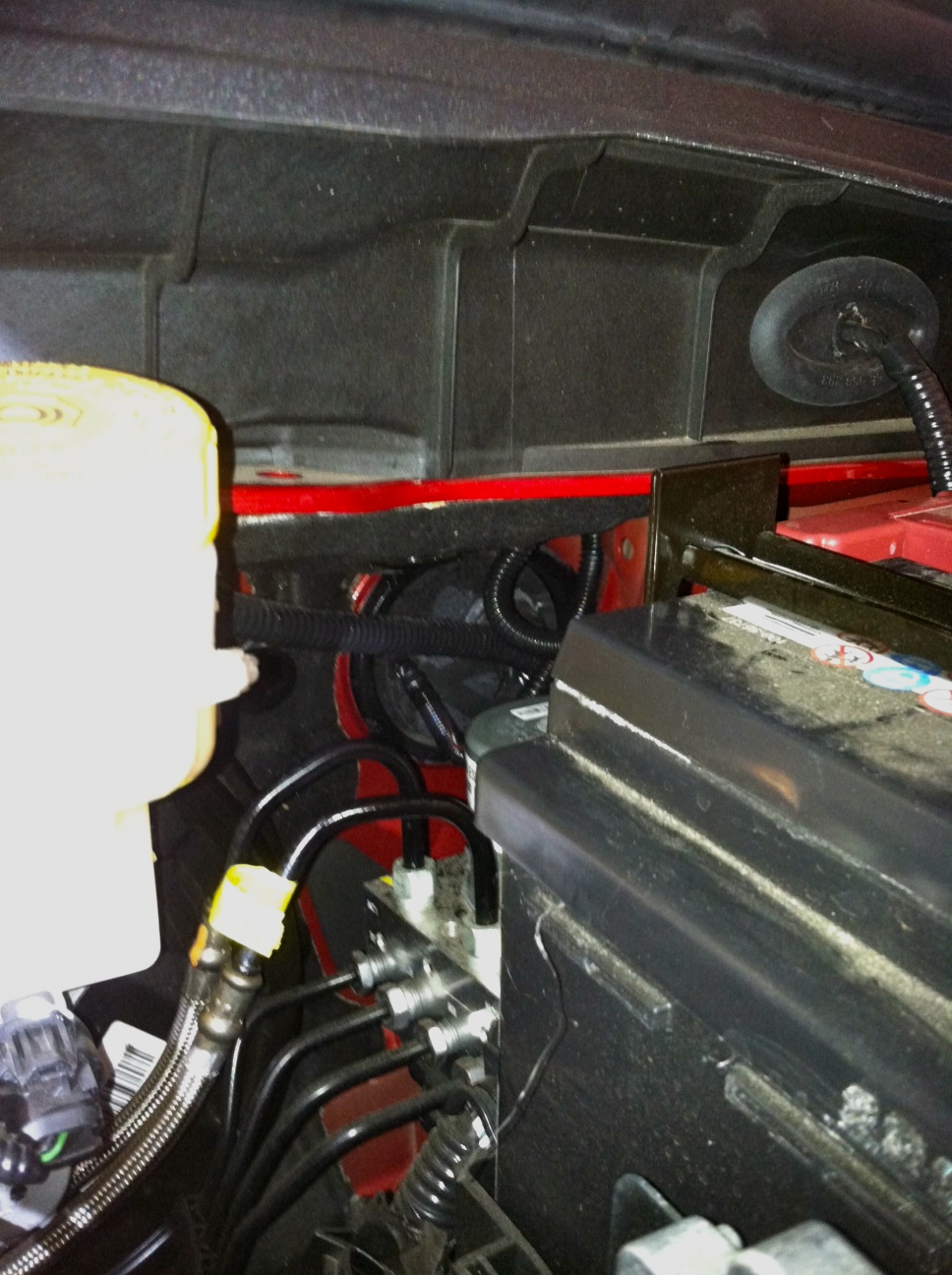
Let's get some power to the back of the car. Get yourself 15 feet of #12 or #10 black and red wire. Cut a hole in the large grommet in the firewall and pass the wire through it. It's easy to find right behind the battery. You can reach it from under the dashboard too.

Do not connect the wires to the battery just yet.


Now that your wire is pulled through from the engine bay, remove the covers from the drivers side door sills and feed the wire through to the back of the car. You will stop when you get to the back seat. Remove the flooring from the trunk to expose the spare wheel. Feed a cable snake from the trunk side of the seat to the drivers side door. Attach your cable and gently pull it back to the trunk. 


You may now replace the flooring in the trunk. I terminated the trunk end of the wire with 45Amp Anderson PowerPoles. In turn the cable will feed a fuse box for other equipment. Return to the engine bay and install a 30Amp fuse on BOTH the red and black wires then attach them to the battery. Test the wiring (you should have 12V at the trunk end of the cable). If all is well install the radio into the trunk.


Using the supplied remote head mounting kit, connect one end of the long black telephone style cable to the radio body and feed the other end under the rear seat, across the trans tunnel and into the drivers zone. Do the same with a remote speaker. The microphone will require you to obtain a 6P6C telephone cable. Make sure that it is wired 1-1 rather than 1-6 (reversed). I ended up buying a 25' cable from eBay and then cutting it to length before installing a new plug on the end. As you can see in the above picture, I fed all my control wires through a piece of cable dressing so as to keep them all together.


 Finally, using an RJ45 cable coupler, connect the mic to the mic cable. Also connect the head to the black control cable and position all items in your favoured position. I used 3M double sided tape to secure the head to a spot just below the radio control screen.

Don't forget to put your car back together again.

Monday, 10 October 2016

2015 Chevy Sonic Antenna Install

I installed 3 antennas onto a 2015 Chevrolet Sonic this weekend. It was a simple install that will in turn be attached to some ham radio gear that is yet to be installed into that vehicle.

After discussion with the owner it was decided to install the main antenna supporting the voice radio into the middle of the roof. This will allow the optimal radiation pattern for the antenna. However, this would require removing the head liner from the vehicle to allow access to the center of the roof. A compromise was found by installing the antenna directly above the rear passenger dome light which was only slightly off-center to the vehicle.


The Dome light is easily removed by gently pulling on it. It will fall out and be held by it's supply cable. Remove the supply cable by pressing the clips found on either side of the connector. Remove the light and put it in a safe place for later restoration.

Now you are left with a rectangular space. Find the center of the space by drawing an X from the diagonally opposite corners of the hole. Drill a small pilot hole at the center of the X from the inside to the outside of the car.

Now drill out the hole you've made with increasingly larger drill bits until you have a hole that will correctly accept your antenna mount. My NMO mount required a 3/8ths hole but others require 1/2 inch or even 3/4 inch holes. Increasing the size of the hole in steps makes for a neater hole and reduces the risk of buckling the metal with the torque of the drill.

Clean up any shards and splinters with a slightly larger drill bit but be careful not to create a larger hole. Install the antenna mount into the hole you've made making sure to weather seal it where necessary.

Now we need to pull the coax from the mount into the back of the vehicle (the radio will be going into a pocket in the trunk). Feed a snake (I used a wire coat hanger) from the back of the car to the antenna mount, attach the coax to it and then gently pull it towards the back of the car.


Depending upon the style of the mount used you may have to insulate the bottom parts of the mount so as to prevent them shorting on the light. A strip of duct tape would be ideal for this. As you can see, my mount had a plastic cover already. Reconnect the dome light and reinstall it back into its hole. We are finished with this part of the installation.


I did say that I installed 3 antennas. For the remaining 2 I used a combined GPS antenna with NMO mount. This was installed at the back drivers side of the roof. I didn't get any pictures of the install as it started to rain just as I had drilled my pilot hole. But, here's the finished product ...


The flat part at the rear of the mount is the GPS antenna whilst the front part is an NMO mount. As you can see, the rain made taking pictures of the install impossible. 


Thursday, 7 April 2016

Ham radio install in a 2015 Nissan Rogue

I bought a new car recently. It's taken me over a month to work out how to install my ham radio gear into it. Finally I discovered a few websites and chat forums where guys were installing high end stereo equipment into their vehicles. I got much advice from them. The below details my adventures.

All my radio's can be remote mounted. This means that the actual radio can be separated from the control head by means of a control cable. I've taken to installing my radio's in the back of the car with the control heads on the dashboard.

Far at the back of the car in the trunk area is an access panel that leads to the spare wheel. There's also a tray that runs the width of the car. It's just deep enough to place all my radio gear into.


So now that the radio's are secured how do they get connected to the control heads in the front of the vehicle? That had me stumped for a while. Then I noticed these wires arriving from the back seat side of the car. Look closely and you'll see them either side of the hinge straps that hold the trunk floor in place. Where do they come from?


I was able to remove the seat cushion from the back seat. It's held on by just 2 clips. Can you see that cable loom at the bottom that vanishes under the seat back cushion?


Back to the spare wheel well. Remove the wheel jack and tools from the bin they are in and you'll see a square hole. In the hole is another cable loom. Remove the 3 Philips head screws that hold the tool bin in place to reveal the whole loom. It goes to the rear light cluster.


I inserted a cable fish into the gap that the cable loom used to get from the back seat to the trunk. I attached all my various wires (power, control, microphone, speaker and some spares) and pulled them all through from the trunk to the back seat. Carefully remove the plastic strip that's right at the door threshold to reveal another cable loom. The loom goes along the door sill, past the seat belt anchor and into the front. Remove the front door cover to expose more loom. I used the existing cable anchors to hold my new cables.


Having pulled all my cables from the back to the front I put the back seat and trunk back together again. The cables will be fed into the dashboard and installed into the control heads, microphones and speakers. Power also needs to be connected to the battery so a path through the firewall is required.

The usual way through a firewall is to find the vehicle's cable loom and piggy-back through the same hole. Good luck with that!! An inspection of the underside of the dashboard does not reveal any obvious candidates and neither does the engine bay. I was able to trace the engine hood release cable to the driver's side of the firewall but could not find it on the engine side. That's when I went back to the Nissan chat forum. Turns out that you have to remove the wheel and the fairing!!!


A closer look inside the wheel arch, behind the fairing reveals some useful grommets and even a spare one! Woohoo!! Where's my cable fish?


So now I had to find a tidy path from the cable tunnel along the door sill, up underneath the dashboard and out of the hole I found. Removing the plastic panel next to the door revealed a huge loom. I followed it and it led me to the hole I'm going to use.  Incidentally, the heavy duty red and blue wires in the picture are switched 12V and constant 12V from the car battery going to and from the ignition. You could tap in there if you wanted a switched source. Max current is 40 Amps as dictated by a fuse at the battery terminal.


So with my cable fish (is it a fish or a snake? I have always heard it that you snake a cable with a fish?) inserted through my hole from the wheel arch side, I pulled the power cables through to the engine side. Then I found a path from the wheel to the engine and popped out right by the battery.


Connection to the battery was made with two fused 30 Amp pigtails; one fuse for the positive battery terminal and the other for the negative battery terminal. I also connected the engine block to the battery directly as well as the body work to the battery directly. All connections were made with #10 wire and waterproof crimp-n-shrink connectors.
 

Wednesday, 23 March 2016

$100 APRS Tracker Mk2

Way back (2001) before they invented Internet 2.0 I built an APRS tracker for less than $100. It was a collection of stuff slapped together into a box and sported a TinyTrak tracker, GPS receiver and a 2 watt transmitter. In its day it was quite an achievement. Most APRS implementations would run over $150 and require an old TNC and a full FM transceiver. GPS's in those days were also big and ugly too. To this day I still get requests for the radio I used.

Well, over the years it has had updates and repairs and even had a 10W linear amplifier added to improve its range but yet it was still a pile of components slapped together into a somewhat large box. It finally gave up the ghost and forced me to go a different route. I briefly looked at creating my own tracker but abandoned it due to time constraints and other projects.

That was then. This is now. I bought a new car recently and am in the throws of moving my radio gear into it. Whilst I have a "black box" radio that will do APRS very well I still want to run my own bespoke APRS tracker. So that led me back to the $100 APRS Tracker.

Looking around the shack I found an old Motorola SM50 left over from a D-STAR HotSpot project. All I needed now was the tracker and a GPS receiver. Then I remembered that I had looked at this project a few years back. At that time I was playing with Ublox NEO-6 GPS modules for use in NTP time servers. These are sub $10 GPS receivers for adding to your projects. They are trivial to use requiring just 3.3v and an antenna. As you can see from the below picture I was able to integrate one into a tracker prototype (it's that white square blob).


But it didn't work. Or rather, it worked badly. Whilst it would talk to the config software when attached to the PC and indeed would send a beacon it wouldn't send any position data. Now I remember why I abandoned it. Having a little more time now I took another look. 

Turns out that the problem was trivial. In its old form (pictured above) the GPS was spitting out position data at 9600bd but the PIC microcontroller was expecting the data at 4800bd. DUH!! The fix was to ground one of the config pins on the GPS thus forcing it into 4800bd mode. In writing this page and getting the files etc together I've come across some auto detecting firmware that makes this problem go away. And I can tell you that it works wonderfully! If only I had bothered to look a little harder the first time around.

So let's do some accounting ...
  • Motorola SM50 FM transceiver    $30  ebay
  • Tracker PCB                                  $8    oshpark.com
  • Ublox NEO-6 GPS RX module     $12  ebay
  • PIC 16F628 microcontroller          $3    ebay
  • SMA antenna connector                 $1    hamfest
  • Motorola pre-wired 16 pin plug     $4    ebay
  • GPS "hockey puck" antenna          $5     ebay
  • 1/4 wave 2 meter antenna               $8    ebay
  • Mag mount for 2M antenna            $14  ebay
That's a grand total of $85. And if you already have some spare 2M antennas kicking around you can shave another $22 of that for a potential $63.

So I've parked all the board stuff on oshpark.com for you to order. You'll get 3 boards for $22. The PCB will allow you to use any current Ublox NEO-x GPS modules. They'll spit out 9600bd data so you'll have to use 9600bd compatible PIC APRS code. Luckily I've linked to that below. You can also change the PIC for a slightly better one which will have more facilities. 


Order from OSH Park

Eagle files for download ...


PIC microcontroller code for download ...

kf163tracker-2.0.2.iso It's a bootable Linux disk. Contains firmware, manuals and config software.

Thanks to DK7IN for his original idea and PE1ICQ for his expansion of this idea and his excellent code.