Showing posts with label Antenna. Show all posts

Saturday, 18 April 2026

Using AI to combat RFI in a power supply

Followers of my rantings will have seen this post where I talk about the issues I am having with a cheap switch mode power supply unit (SMPSU) and its interference with my radio reception.

Just for grins I thought I'd try asking Claude.AI for advice on mitigating this RFI. What it told me went against everything I had been taught about combating RFI in the radio shack.

Let's start with some pictures. The first picture is of my Afedri SDRNet Software Defined Radio tuned to the low end of the Medium Wave (AM) broadcast band. I am using GQRX as the front end. You can see quite a number of very aggressive signals that are not desired.

If you look at the waterfall above (the blue/yellow bit) one can clearly see very strong individual single carriers that in some cases are louder than my local radio stations at over -35dB.

How do I know that this particular SMPSU is responsible for this RFI? When I unplug it this happens ...

What a difference!!! No change in my noise floor was observed. It normally sits around -95dB. I live in a significantly urban area and so my neighborhood is filled with other peoples electronics devices which add to the noise floor. 

So how do I fix this? Conventional wisdom dictates that I build a filter and apply it to the output of the supply before it connects to my radio equipment. In this case however, my SDR is not powered by the switch mode power supply. So where is the noise coming from? Again, conventional wisdom tells us that the interference is radiating along the wires connected to the output side of the SMPSU and then being picked up by the antenna on the SDR. This appears to be correct as disconnecting the antenna from the radio produces no RFI issues. Adding an AM band stop filter significantly reduces the RFI and its related harmonics (iterations of the interfering signals that flood the radio all the way up to its maximum range).

Note how the noise floor has dropped 25dB and so have the FRI signals too. Clearly they are being received by the radio over its antenna. Lets remove the filter and perform one final test. Lets disconnect the wires from the output side of the SMPSU.

Yes, removing the wires from the output side of the SMPSU also removed the RFI. Removing the filter also increased the noise floor by 25dB. So we can surmise that conventional wisdom is correct in that the RFI is indeed leaking out of the SMPSU via its output wires.

So to recap our findings; 

  • The Switch Mode Power Supply Unit (SMPSU) is creating RFI
  • RFI is being radiated on the wires connected to the SMPSU output
  • The band stop filter is not sufficient to combat this RFI

So lets ask Claude. I asked the question "How might I mitigate the RFI being emitted from an cheap switch mode PSU?". After a second or so of thought Claude responded

Great practical question! Here are the main mitigation strategies, roughly in order of effectiveness and ease of implementation:

1. Input EMI Filter (Most Important)

As discussed, this is your first line of defense. You can:

  • Buy a pre-made IEC inlet filter module — these are cheap (a few dollars) and combine X/Y capacitors and a common-mode choke in one package. Simply wire it between the mains and the PSU input.
  • Look for ones rated at the PSU's current draw with attenuation specs in dB across the frequency range you care about.

2. Common-Mode Choke on the Input

If you want to go further, add a toroidal common-mode choke wound on a high-permeability ferrite core (Fair-Rite, Wurth, TDK all make suitable cores). Wind both the live and neutral together through the same core — this attenuates common-mode noise without affecting the 50/60Hz supply current.

3. Ferrite Clamp-On Cores

The quick and dirty approach — snap ferrite clamp-on chokes onto the input cable as close to the PSU as possible. Multiple cores stacked together increase attenuation. These are the things you see as lumps on laptop power cables. They won't fix a really bad PSU but can take the edge off.

4. Shielding the PSU

  • House the PSU in a grounded metal enclosure if it isn't already — this addresses radiated RFI rather than conducted.
  • Ensure the shield has a solid, low-impedance connection to earth ground.
  • Any gaps or apertures in the enclosure should be smaller than λ/20 of the highest frequency you're concerned about.

5. Output Side Filtering

While less effective for RFI back into the mains, adding filtering on the DC output helps protect sensitive downstream circuits:

  • A pi filter (capacitor → inductor → capacitor) on the DC output rail
  • Keep the inductor value modest (a few µH) to avoid instability with the PSU's feedback loop
  • Use low-ESR capacitors

6. Proper Grounding and Cable Routing

  • Keep input and output cables physically separated — they can couple noise back if run together
  • Use shielded cable on the output if running to sensitive equipment
  • Ensure a solid single-point earth ground

7. Replace the PSU

Honestly, with very cheap PSUs, the economics sometimes favor just buying a better unit. PSUs from reputable manufacturers (Mean Well, for example) are already designed with proper EMI filtering built in and have passed regulatory testing. A Mean Well unit costs only slightly more than a no-name unit plus the remediation parts.


Practical Approach

If this is a specific interference problem you're troubleshooting, a good workflow is:

  1. Start with a clamp-on ferrite on the input cable — costs almost nothing and takes 30 seconds
  2. If insufficient, add a pre-made IEC EMI filter module
  3. If still problematic, add a metal enclosure with proper grounding
  4. If you're still fighting it, the PSU is probably beyond economical remediation — replace it
It appears Claude thinks the issues are on the INPUT side of the SMPSU. This goes against conventional thinking. The mitigation was broken down into 4 manageable steps. Lets try them.

1) "Start with a clamp-on ferrite on the input cable". You've seen these a everywhere. You probably have some knocking about in your junk box. I have a large stash of these collected over the years from other projects or junk sales. I'll install 1 on the input side power cable and if it works we should see some drop in the level of the interference which is currently over -35dB.


As seen on the left I added a single clamp-on ferrite. It did actually do something. We've gone down from -35dB to about -53dB (see above). Lets round it up and call it -55dB. That's actually a significant improvement. 20dB is around a quarter of the original signal. However, its still too much by a long way. I tried adding more clamp-on ferrite's but it seemed to make no difference.

While doing this I also noted that when the output cables are connected but yet the powered devices are not yet turned on there is no RFI. Only when the powered devices draw current does the RFI appear. This sent me down a short rabbit hole to see if it was in fact one of the many devices (mostly Raspberry Pi's based SDR's) powered by this SMPSU.

So on to step 2, "Add a pre-made IEC EMI filter module". I found this device on Amazon which was promptly ordered. As the SMPSU does not have an IEC plug I bought one with pigtails. Lets get it installed.


No discernible difference. Arguably things got worse by 10dB. One of the important things to note with the EMI filter is that while it has 3 incoming conductors it has only 2 outgoing conductors. The ground is not presented for connection to the SMPSU. Lets try "yoking" the ground and connecting it back onto the SMPSU.


Maybe one or two dB's of improvement with the earth attached but its hard to tell. Certainly not the improvement I was looking for. 

Step 3 says to mount it inside a metal enclosure. The SMPSU already has a metal enclosure. I opened it up to check it was grounded and it is. 

So that leaves Step 4: "the PSU is probably beyond economical remediation - replace it". Hmm. Does Claude have shares in a PSU factory? This is not a possibility for me due to financial constraints.

So has Claude failed to mitigate my RFI issue? Why did it not offer me some output/DC side solutions? For now I'll chalk this up as an AI fail.


Wednesday, 23 October 2024

Satellite Exploits

 This is a reprint of a few pages from my old g7ltt.com website originally posted in 2002 ...


Firstly lets look at my station. I own the ubiquitous Yaesu FT-847 transceiver. This radio is very commonly found in the stations of many a satellite enthusiast. I have beam antennas for 2mtrs, 70cms and an MMDS down-converter with dish for 13cms (2.4GHz) all of these antennas are mounted on a cheap azimuth and elevation rotator arrangement by Satelectronics.

I have owned this radio for about a year with the intention of getting active on the satellite bands and was finally able to install my antenna system onto my new house in the early summer of 2002. All was not well. I bought one of the first Sat-El rotor systems that were made and it came with a few surprises. Firstly, the software was severely lacking. So much so that I took to developing my own program so that I could make my satellite prediction software control the antennas. QA was also a serious issue. One of the 2 rotators wouldn't work. After several trips to the roof and almost 6 weeks in waiting I finally got a replacement rotor. Having proved that the new one worked I took it apart to compare it with the broken one. The broken one was missing a very large capacitor! It never worked so how could it have passed the manufacturers QA process?


Aligning the antennas was another pain. The antennas must be accurately mounted onto the rotator so that when the rotators think they are looking at the Pole Star the antennas are too. In this way whenever the software controlling the rotators wants to look at a given point in the sky the antennas will correctly look there. This was not an easy task. It took me almost 6 months to complete this stage of the alignment. I couldn't seem to get the rotators to line up with anything.

A few nights ago I was watching "The Dish" on video. Its the story of the Parkes Radio Telescope in Australia. This was the dish that brought the TV pictures of Neil Armstrong's Apollo 11 moon walk back to the world. The story told in the movie is apparently true and it chronicles the goings on during the 2 weeks around the moon walk. Parkes was the only dish in that part of the world capable of receiving the pictures as the moon was only visible from Australia at the time. Well Parkes computer had a problem just a few hours before the big event and they lost contact with the space craft. After an hour of bluffing NASA about land line problems they finally found the space craft by randomly pointing the dish at the moon and waving it around a bit. This gave me an idea!!

So picture the scene. Its 10:30PM. Its dark. Its DAMN cold. The moon is out. Mark is on the roof trying to work out why his antennas are not pointing at the moon when he tells them too. I figured that I could align the antennas with the moon as my point of reference rather than the Pole Star. I can see the moon. I don't know what the Pole Star looks like. I start by guestimating the amount of error between my antennas and the moon's location. I guess 20 degrees. I go down to the basement where I control them from and fiddle with the settings. I go back up onto the roof. I reckon I made it worse. I go back down to the basement. And so on for about half an hour.

I'm getting cold and annoyed. It's getting late and the neighbors dog keeps barking at me up on the roof. I retire to the bedroom to spend some time with my wife before she forgets what I look like. On the way I fall over my laptop computer. A light goes on! I have a wireless network card in my laptop and some remote control software on my computer in the basement. Quick as a flash I'm back on the roof with my laptop. Now I can see what I'm doing!! Within about 5 minutes I was able to align the antennas so that they pointed at the moon. As the antennas are only about 6 feet above the roof of my house I was able to look from the back of them up to the moon and see that they were perfectly lined up. Back down the ladder and off to bed.

Sunday morning and I'm up early and down in the shack. I run up Nova (satellite tracking program) on my computer and find that I'm just in time for a PacSat pass. I instruct my antennas to point to it. A quick check of  Amsat's Operational Satellites page tells me what frequency I need to listen on. Sure enough, there's a whole bunch of data being transmitted. Result! My antennas are looking at a satellite. I don't have anything set up do receive the data so I just listen to it. Not quiet 10 minutes of data was heard here at KC2ENI QTH.


Next up was a crack at AO-40. This is what I started building my satellite system for. I have an MMDS down converter and a 3 foot BBQ grill dish (more about this here) which allows me to listen to the 2401MHz band. This is where all the activity is now as AO-40 has had some sort of unexplained accident which killed off all its other facilities. Sure enough when the satellite came around later that day I was hearing some hams sending each other SSTV pictures. I tried to decode the pictures but I wasn't able to get a good enough signal from the satellite. I was able to decode the telemetry beacon with some success as you can see from the screen capture above.

You can see I was only getting about 40% of the data packets from the telemetry beacon. I'm not sure quite why that is but I suspect that it has something to do with interference from all the 2.4GHz (2401MHz) gizmos we have around the house like our wireless network and some CCTV cameras.

On the next pass I'll turn all the 2.4GHz stuff off and see of it makes an improvement on the telemetry. If so it looks like I'll be spending a lot of time hard wiring the network devices to the main switch here in my shack.


Tuesday, 18 October 2016

Ham radio install in a 2015 Chevy Sonic

My girlfriend has a Chevy Sonic. She also has a newly minted ham licence. And as if all that wasn't enough it was recently her birthday. She has a Yaesu FTM-100D. The job of installing it fell to me.

In a previous posting I installed the antennas onto her car.

On this outing we'll be installing the radio itself. The main body of the radio will reside in the cargo shelf at the back of the car whilst the control head, mic and speaker will be mounted in the front.

Let's get some power to the back of the car. Get yourself 15 feet of #12 or #10 black and red wire. Cut a hole in the large grommet in the firewall and pass the wire through it. It's easy to find right behind the battery. You can reach it from under the dashboard too.

Do not connect the wires to the battery just yet.


Now that your wire is pulled through from the engine bay, remove the covers from the drivers side door sills and feed the wire through to the back of the car. You will stop when you get to the back seat. Remove the flooring from the trunk to expose the spare wheel. Feed a cable snake from the trunk side of the seat to the drivers side door. Attach your cable and gently pull it back to the trunk. 


You may now replace the flooring in the trunk. I terminated the trunk end of the wire with 45Amp Anderson PowerPoles. In turn the cable will feed a fuse box for other equipment. Return to the engine bay and install a 30Amp fuse on BOTH the red and black wires then attach them to the battery. Test the wiring (you should have 12V at the trunk end of the cable). If all is well install the radio into the trunk.


Using the supplied remote head mounting kit, connect one end of the long black telephone style cable to the radio body and feed the other end under the rear seat, across the trans tunnel and into the drivers zone. Do the same with a remote speaker. The microphone will require you to obtain a 6P6C telephone cable. Make sure that it is wired 1-1 rather than 1-6 (reversed). I ended up buying a 25' cable from eBay and then cutting it to length before installing a new plug on the end. As you can see in the above picture, I fed all my control wires through a piece of cable dressing so as to keep them all together.


 Finally, using an RJ45 cable coupler, connect the mic to the mic cable. Also connect the head to the black control cable and position all items in your favoured position. I used 3M double sided tape to secure the head to a spot just below the radio control screen.

Don't forget to put your car back together again.

Monday, 10 October 2016

2015 Chevy Sonic Antenna Install

I installed 3 antennas onto a 2015 Chevrolet Sonic this weekend. It was a simple install that will in turn be attached to some ham radio gear that is yet to be installed into that vehicle.

After discussion with the owner it was decided to install the main antenna supporting the voice radio into the middle of the roof. This will allow the optimal radiation pattern for the antenna. However, this would require removing the head liner from the vehicle to allow access to the center of the roof. A compromise was found by installing the antenna directly above the rear passenger dome light which was only slightly off-center to the vehicle.


The Dome light is easily removed by gently pulling on it. It will fall out and be held by it's supply cable. Remove the supply cable by pressing the clips found on either side of the connector. Remove the light and put it in a safe place for later restoration.

Now you are left with a rectangular space. Find the center of the space by drawing an X from the diagonally opposite corners of the hole. Drill a small pilot hole at the center of the X from the inside to the outside of the car.

Now drill out the hole you've made with increasingly larger drill bits until you have a hole that will correctly accept your antenna mount. My NMO mount required a 3/8ths hole but others require 1/2 inch or even 3/4 inch holes. Increasing the size of the hole in steps makes for a neater hole and reduces the risk of buckling the metal with the torque of the drill.

Clean up any shards and splinters with a slightly larger drill bit but be careful not to create a larger hole. Install the antenna mount into the hole you've made making sure to weather seal it where necessary.

Now we need to pull the coax from the mount into the back of the vehicle (the radio will be going into a pocket in the trunk). Feed a snake (I used a wire coat hanger) from the back of the car to the antenna mount, attach the coax to it and then gently pull it towards the back of the car.


Depending upon the style of the mount used you may have to insulate the bottom parts of the mount so as to prevent them shorting on the light. A strip of duct tape would be ideal for this. As you can see, my mount had a plastic cover already. Reconnect the dome light and reinstall it back into its hole. We are finished with this part of the installation.


I did say that I installed 3 antennas. For the remaining 2 I used a combined GPS antenna with NMO mount. This was installed at the back drivers side of the roof. I didn't get any pictures of the install as it started to rain just as I had drilled my pilot hole. But, here's the finished product ...


The flat part at the rear of the mount is the GPS antenna whilst the front part is an NMO mount. As you can see, the rain made taking pictures of the install impossible. 


Thursday, 7 April 2016

Ham radio install in a 2015 Nissan Rogue

I bought a new car recently. It's taken me over a month to work out how to install my ham radio gear into it. Finally I discovered a few websites and chat forums where guys were installing high end stereo equipment into their vehicles. I got much advice from them. The below details my adventures.

All my radio's can be remote mounted. This means that the actual radio can be separated from the control head by means of a control cable. I've taken to installing my radio's in the back of the car with the control heads on the dashboard.

Far at the back of the car in the trunk area is an access panel that leads to the spare wheel. There's also a tray that runs the width of the car. It's just deep enough to place all my radio gear into.


So now that the radio's are secured how do they get connected to the control heads in the front of the vehicle? That had me stumped for a while. Then I noticed these wires arriving from the back seat side of the car. Look closely and you'll see them either side of the hinge straps that hold the trunk floor in place. Where do they come from?


I was able to remove the seat cushion from the back seat. It's held on by just 2 clips. Can you see that cable loom at the bottom that vanishes under the seat back cushion?


Back to the spare wheel well. Remove the wheel jack and tools from the bin they are in and you'll see a square hole. In the hole is another cable loom. Remove the 3 Philips head screws that hold the tool bin in place to reveal the whole loom. It goes to the rear light cluster.


I inserted a cable fish into the gap that the cable loom used to get from the back seat to the trunk. I attached all my various wires (power, control, microphone, speaker and some spares) and pulled them all through from the trunk to the back seat. Carefully remove the plastic strip that's right at the door threshold to reveal another cable loom. The loom goes along the door sill, past the seat belt anchor and into the front. Remove the front door cover to expose more loom. I used the existing cable anchors to hold my new cables.


Having pulled all my cables from the back to the front I put the back seat and trunk back together again. The cables will be fed into the dashboard and installed into the control heads, microphones and speakers. Power also needs to be connected to the battery so a path through the firewall is required.

The usual way through a firewall is to find the vehicle's cable loom and piggy-back through the same hole. Good luck with that!! An inspection of the underside of the dashboard does not reveal any obvious candidates and neither does the engine bay. I was able to trace the engine hood release cable to the driver's side of the firewall but could not find it on the engine side. That's when I went back to the Nissan chat forum. Turns out that you have to remove the wheel and the fairing!!!


A closer look inside the wheel arch, behind the fairing reveals some useful grommets and even a spare one! Woohoo!! Where's my cable fish?


So now I had to find a tidy path from the cable tunnel along the door sill, up underneath the dashboard and out of the hole I found. Removing the plastic panel next to the door revealed a huge loom. I followed it and it led me to the hole I'm going to use.  Incidentally, the heavy duty red and blue wires in the picture are switched 12V and constant 12V from the car battery going to and from the ignition. You could tap in there if you wanted a switched source. Max current is 40 Amps as dictated by a fuse at the battery terminal.


So with my cable fish (is it a fish or a snake? I have always heard it that you snake a cable with a fish?) inserted through my hole from the wheel arch side, I pulled the power cables through to the engine side. Then I found a path from the wheel to the engine and popped out right by the battery.


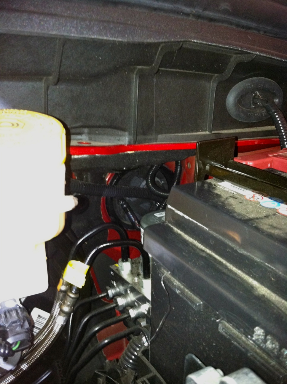
Connection to the battery was made with two fused 30 Amp pigtails; one fuse for the positive battery terminal and the other for the negative battery terminal. I also connected the engine block to the battery directly as well as the body work to the battery directly. All connections were made with #10 wire and waterproof crimp-n-shrink connectors.