There's something very satisfying about making your own stuff. As you'll have seen by my previous posts I design a lot of my own circuits. To this end I've built a Surface Mount Device Reflow Oven.
I was inspired by this youtube video. The thing that impressed me about it was the price; small reflow ovens can cost upwards of US$500. The toaster oven used in the video is still (March 2015) on sale at Walmart for less than US$20. But like most things based on an Arduino, not only does it require an Arduino board at some US$30+ but it needs a shield to connect all the temperature sensing and heating elements etc at a further US$35. So that would make the total something like US$100 or more. Still not ideal.
So thinking that I could do better I set about designing my own "embedded Arduino" based controller. It would have all the same facilities as the one in the video but everything would be contained on a single PCB where possible.
This is what I came up with. The board above contains an AC power supply, LCD interface, temperature sensor, interface buttons, buzzer, FTDI serial interface and of course, an Arduino.
So then all I needed was firmware for the Arduino. There was no point trying to write my own. It's not as if I've had an original idea here. Casting about the 'net I came across this website where IanJ describes his journey creating a similar oven. I downloaded Ian's code and set about adapting it to my board. It was quite easy really. I simply needed to move some pin assignments around and change some of the outputs from low to high etc. My modified version of the code can be found below. It still requires the library from Ian's website (don't forget to modify the library for Arduino IDE 1.x+).
My design differs from Ian's slightly in that I use a PNP transistor to toggle the relay that in turn powers the heater elements. I've also used the analog pins in digital mode so that I could make the board layout easier for a milling machine or home brewers doing single sided boards and likewise I have not used the traditional LCD pins but rather moved them to other pins for the same reasons. Other than that we've come up with more-or-less the same design.
If you want a copy of the board you can buy it from Oshpark. Be aware that there is a minor error on the PCB. The "fix" is to raise pin 21 of the Arduino such that it does not connect with the IC socket. I had inadvertently connected that pin to ground when it should have been either pulled up or left floating.
Parts list and costs ...
"Rival" brand toaster oven - $18.47 @ Walmart
Solid state relay - $1 @ ebay
Welding blanket - $18 @ ebay
"K" type thermocouple (minimum 350c) - $1 @ ebay
PCB - $10 @ Oshpark
Arduino - $3 @ DIPMicro.com
LCD - $2 @ ebay
R's, C's etc, - $3 @ junque box
AD595 temperature sensor - $3 @ ebay
Total = $60 or thereabouts
The usual files in Eagle format and GCode for your CNC mill ...
YARO.ino
YARO.pdf
YARO.brd
YARO.sch
YARO.bot.etch.ngc
Friday, 20 March 2015
Saturday, 7 March 2015
Ebay 3020 desktop CNC router
I bought one of these 3 axis CNC routers via ebay. My goal is to make my own PCB's with it. Well, yeah; that's my goal. But in the 9 months I've owned it I've not yet been able to get a satisfactory piece of work from it. As is usual with most things from China via Ebay, the documentation was non-existant. I got most of my information from other frustrated owners on various mailing lists and message boards.
| Sales picture from ebay |
I say "properly" as the supplied controller (the thing in the black box) was pretty lacking in its features. Not only that but when I tried to use the demonstration CNC projects supplied with the Linux software the router became intermitant. Investigation of the controller box revealed that the enclosed circuit board was not grounded at all!! It relied on a single screw thread poking through a mounting hole. Unfortunately the screw head was covered in paint. A wire brush fixed the paint problem and a few other ground cables added here and there brought the lighted power switch into operation. Great, now it would route the demonstration piece.
![]() |
| Rear panel of the controller |
![]() |
| Inside of the controller. Note linear PSU and 2 control boards |
![]() |
| Spindle control not connected to anything |
![]() |
| Limit and bit spindle outputs not connected to anything |
![]() |
| Limit switches brought to the back of the control box |
![]() |
| A-axis output just below the left white connector |
Since starting on this journey I have run across some other websites that have also found the same issues as I have. This one is by far the most detailed.
Friday, 6 March 2015
Build your own "Internet"
By now you've probably seen this sketch from the TV show "The IT Crowd"? Jen is fooled into believing that a small black box with a flashing light on the top is in fact what the Internet looks like.
I gave a talk recently at a gathering of Shortwave radio listeners. I decided that I would demonstrate the "Internet" as part of my talk so I set about building one of my own. It's incredibly simple and requires just a few $$ of parts and a black plastic box.
I got the above circuit from the real Internet. Note that the circuit has 2 LED's. To make a clone of the original "Internet" one needs only to use a single LED however, the two LED's gave me an idea ..... build a second device which would use both LED's into a smaller box and call it "The Internet V2.0". After all, Moore's Law dictates that everything becomes smaller, cheaper and has more facilities.
My boxes had a 9V battery for power and the circuit was stuck onto the inside of the lid with double sided tape.
It you want to make one of your own you can buy a board from Oshpark
As usual, here are the files in Eagle format along with GCode for your CNC mill ...
555 Internet Flasher.pdf
555 Internet Flasher.sch
555 Internet Flasher.brd
555 Internet Flasher.bot.etch.ngc
I gave a talk recently at a gathering of Shortwave radio listeners. I decided that I would demonstrate the "Internet" as part of my talk so I set about building one of my own. It's incredibly simple and requires just a few $$ of parts and a black plastic box.
I got the above circuit from the real Internet. Note that the circuit has 2 LED's. To make a clone of the original "Internet" one needs only to use a single LED however, the two LED's gave me an idea ..... build a second device which would use both LED's into a smaller box and call it "The Internet V2.0". After all, Moore's Law dictates that everything becomes smaller, cheaper and has more facilities.
My boxes had a 9V battery for power and the circuit was stuck onto the inside of the lid with double sided tape.
It you want to make one of your own you can buy a board from Oshpark
As usual, here are the files in Eagle format along with GCode for your CNC mill ...
555 Internet Flasher.pdf
555 Internet Flasher.sch
555 Internet Flasher.brd
555 Internet Flasher.bot.etch.ngc
Wednesday, 25 February 2015
Give your telescope some teeth
I recently bought a new mount for my Celestron C6 telescope. I am now the proud owner of a Celestron Advanced VX mount. I've not had it outside yet (its still a balmy -10C outside!) but I'm very pleased with its stability and ease of use. I have it set up in my basement and have been getting all the remote control software organised for it so that I can try my hand at some astrophotography when the weather breaks.
As you can see it has a hand controller that will allow me to manually drive the mount to any of over 10000 objects. But for taking pictures I need to have computer control. Luckily this mount comes with that already enabled by way of a RS232 cable that plugs into the bottom of the handset. Only 2 problems here; 1) I have no serial port on my laptop, 2) I must be "tethered" to the mount. I dunno about you but I'd rather have the least amount of cables dragging around my equipment especially when its dark and I can't see them. So wireless is my goal.
One can buy a WiFi enabled remote control device that plugs into the mount but its $100 and as it's WiFi it'll quickly kill the batteries of any mobile device I use with it in place of the PC. Bluetooth is the solution that springs to mind. It has a serial port emulation ability and uses much less power than WiFi.
Other owners have had this idea too. I've seen some interesting attempts to add Bluetooth abilities to this mount. Most of them are a lash up of common off-the-shelf parts and added wires. This solution costs over $130. So whilst sitting on the pot the other day (I do my best thinking in there) I had an idea , "why not connect something directly to the Aux connector on the mount?". Looking at the wiring diagram for the connector we can see that there is 12V of power and 5V TTL serial data available. Indeed, this is what the WiFi adapter uses for it's power and comms as does the GPS receiver addon.
This is what I came up with. One adds a 6 pin telephone cord between the adapter and the Aux socket at which point it'll spring to life. The missing part on the board rendering above is an HC-06 Bluetooth interface. The rest of the stuff is power conversion and such like. Following the "howto" I installed the relevant software and was able to control my mount from my PC. I've also tried it with Sky Safari on my Android tablet too. Works perfectly! I can even remove the hand controller from the mount which will help when up at the club site preventing visitors from playing with my scope when I'm not looking.
I'm calling the project "False Teeth" as the device is not blessed by Celestron.
Files in Eagle format ...
False Teeth.pdf
False Teeth.sch
False Teeth.brd
As you can see it has a hand controller that will allow me to manually drive the mount to any of over 10000 objects. But for taking pictures I need to have computer control. Luckily this mount comes with that already enabled by way of a RS232 cable that plugs into the bottom of the handset. Only 2 problems here; 1) I have no serial port on my laptop, 2) I must be "tethered" to the mount. I dunno about you but I'd rather have the least amount of cables dragging around my equipment especially when its dark and I can't see them. So wireless is my goal.
One can buy a WiFi enabled remote control device that plugs into the mount but its $100 and as it's WiFi it'll quickly kill the batteries of any mobile device I use with it in place of the PC. Bluetooth is the solution that springs to mind. It has a serial port emulation ability and uses much less power than WiFi.
Other owners have had this idea too. I've seen some interesting attempts to add Bluetooth abilities to this mount. Most of them are a lash up of common off-the-shelf parts and added wires. This solution costs over $130. So whilst sitting on the pot the other day (I do my best thinking in there) I had an idea , "why not connect something directly to the Aux connector on the mount?". Looking at the wiring diagram for the connector we can see that there is 12V of power and 5V TTL serial data available. Indeed, this is what the WiFi adapter uses for it's power and comms as does the GPS receiver addon.
This is what I came up with. One adds a 6 pin telephone cord between the adapter and the Aux socket at which point it'll spring to life. The missing part on the board rendering above is an HC-06 Bluetooth interface. The rest of the stuff is power conversion and such like. Following the "howto" I installed the relevant software and was able to control my mount from my PC. I've also tried it with Sky Safari on my Android tablet too. Works perfectly! I can even remove the hand controller from the mount which will help when up at the club site preventing visitors from playing with my scope when I'm not looking.
![]() |
| False Teeth under test |
Files in Eagle format ...
False Teeth.pdf
False Teeth.sch
False Teeth.brd
Sunday, 26 October 2014
The blue smoke theory
One of my managers at work says that everything electrical and electronic requires blue smoke in order to operate correctly. He might be right. Have you noticed how when the blue smoke comes out of your laptop the laptop doesn't work any more? Or when the smoke comes out of your vacuum cleaner it also stops working?
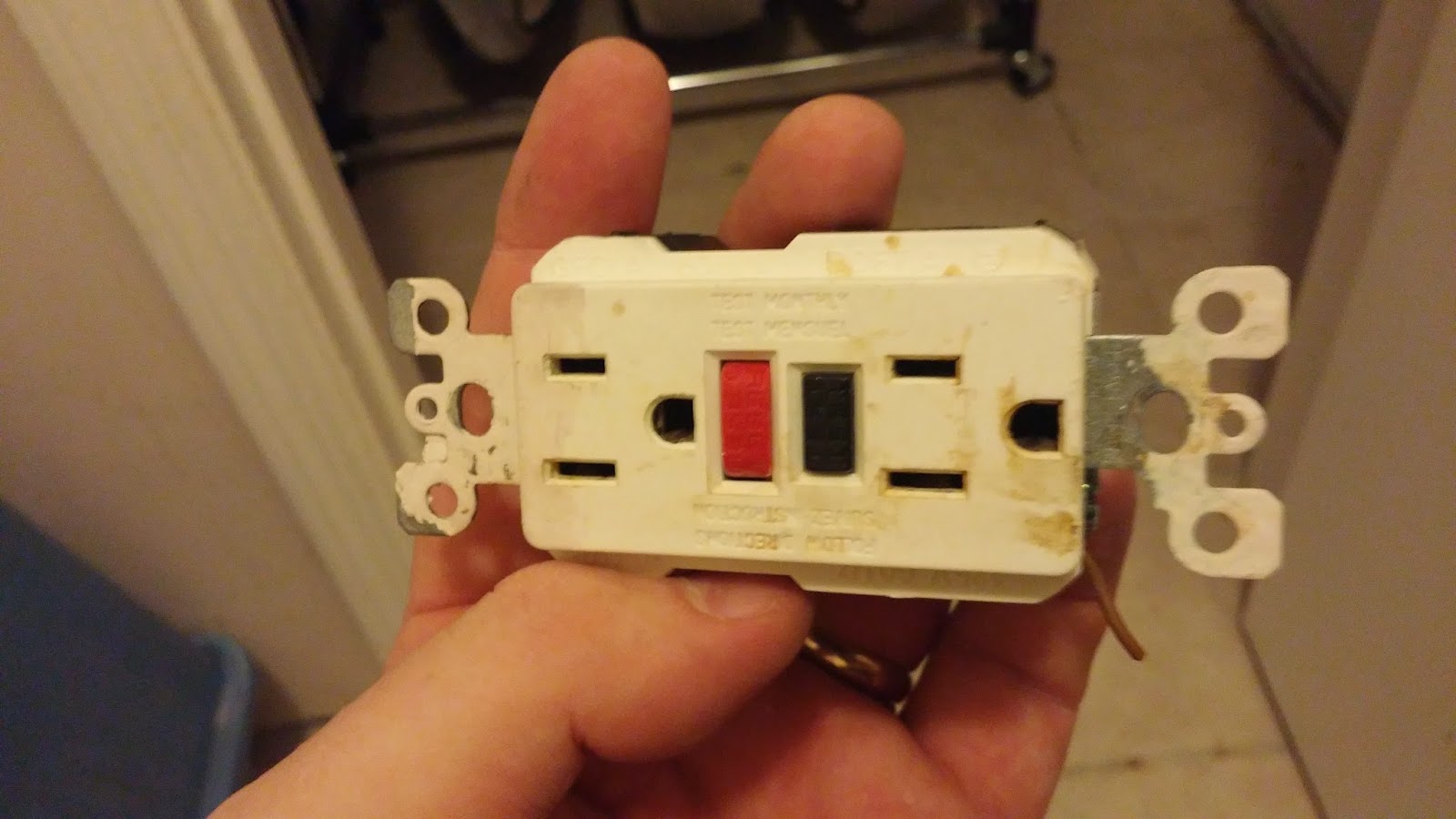
I had a similar demonstration of this theory today. The GFCI/ELCB socket in my downstairs toilet let it's smoke out today. Good job we caught it too otherwise we may not have had a home to live in.
Turns out that there was a loose connection in the return wire. Every time my wife ran her hair dryer it would cause the wires to move under the stress of the current load. The return (a white wire here in the US) would then disconnect itself then reconnect itself causing lots of sparks and arcing and burning. The result was that both the wires and the socket would get hot and so release their smoke.
Good job we caught it. Or rather my dog Rascal caught it. He heard the GFCI arcing then ran into the toilet and started scratching at the wall. It was only when he started barking drawing me into the room that I saw the problem. GOOD DOG!!!!! Extra belly rubs for you.
Monday, 20 October 2014
Yaesu FT-817 Go Kit
Yeah, yeah, yeah. We've all seen Go Kits before. But as Go Kits go I think mine is "up there".
I am a fan of the Pelican case. Y'know the ones? Hard plastic water tight cases that can float and take a beating when traveling. They are usually filled with foam and have cutouts for the equipment they hold.
I bought an IM2200 from my local Best Buy electronics store for $100. This seems to be an average price for them. Ebay did not reveal a cheaper price. It comes filled with 2 layers of "pick-n-pluck" foam which allows you to create shapes by pulling squares of foam out.
In the above picture we can see the lower foam layer. I've created cutouts for the mic, mains PSU, PSU cable and antenna tuner cables. The small box in the top right corner is a Wolphi-Link interface. It's like a PSK31 sound card interface but for your cellphone/tablet. It will also get a cutout.
In this picture we can see the upper layer of foam which holds the FT-817, LDG tuner, spare battery, whip antenna and 1:1 balun. The egg box type foam in the lid also pulls out. I can get 25 feet of RG58 and a 50 foot dipole behind it and still be able to close the lid with ease.
Here's a video of me packing it all away into the case https://www.youtube.com/watch?v=NzgnMb5nZo8
I am a fan of the Pelican case. Y'know the ones? Hard plastic water tight cases that can float and take a beating when traveling. They are usually filled with foam and have cutouts for the equipment they hold.
I bought an IM2200 from my local Best Buy electronics store for $100. This seems to be an average price for them. Ebay did not reveal a cheaper price. It comes filled with 2 layers of "pick-n-pluck" foam which allows you to create shapes by pulling squares of foam out.
In the above picture we can see the lower foam layer. I've created cutouts for the mic, mains PSU, PSU cable and antenna tuner cables. The small box in the top right corner is a Wolphi-Link interface. It's like a PSK31 sound card interface but for your cellphone/tablet. It will also get a cutout.
In this picture we can see the upper layer of foam which holds the FT-817, LDG tuner, spare battery, whip antenna and 1:1 balun. The egg box type foam in the lid also pulls out. I can get 25 feet of RG58 and a 50 foot dipole behind it and still be able to close the lid with ease.
Here's a video of me packing it all away into the case https://www.youtube.com/watch?v=NzgnMb5nZo8
Friday, 10 October 2014
Mobile HF antenna install
I have a 2013 Dodge Journey. It's equipped with all bands from DC to light. It has FM, D-STAR, APRS and HF as well as a few non ham facilities. The problem with the car is that the steel its made from is very thin. The roof for example, flexes with the stress of a VHF antenna. So you can imagine what happens with a tall HF antenna?
A common HF antenna mounting solution is to install a clamp style bracket onto the rear liftgate high up as near to the roof line as possible. This is not possible with my car as the rear liftgate is made of plastic. Plastic and antennas don't work together. One needs a rather large amount of metal underneath the HF antenna so as to act as the counterpoise.
Over the 18 months or so that I've had my vehicle I've tried various mounting methods the best of which was a rather large magnet affair that consumed quite a bit of the roof space. This in turn prevented me from using the roof for other purposes.
My friend Kathy, KT2F, has an expression; "Be a man! I'm a man". She is referring to her willingness to drill holes in her new car to mount antennas. She's not wrong. According to my friend Norman, G4WQS, "a good mechanical join makes a good electrical join". Drilling a hole into the metalwork of the car would create both strong mechanical and electrical connections but only where the metal is thick enough.
I needed to replace the brake light on the back of my car today. Removing the light cluster is a simple matter of removing 2 plastic buttons. That's when I saw it. I finally found a spot to mount the antenna. It's not the best place on the car but it has all the other boxes checked.
You can clearly see the grommet where the cable exits the car behind the light cluster. By dumb luck I had a bracket in the junque box that would fit between the light and the car. 4 holes and some rivets later the mount was installed and a SO239 type antenna connector was attached to the mount. The coax feeding the antenna will feed through the grommet into the car and then on to the back of the radio.
As you can see from the completed installation, it is quite tidy. Click the pictures to get a closer look.
The total job took a little over an hour and that included fishing the coax cable from behind the interior paneling in the back of the car. Tests while parked on the drive show a much improved tune time (I have a screwdriver type antenna) and a broader bandwidth. Indeed, I no longer have to keep retuning when on 40 meters (the lowest band the antenna will cover) whenever I go from one end of the band to the other. Band-to-band tuning is also faster. I can now jump from 40 meters to 10 meters without the auto tuning circuit in the radio timing out.
So now I can tell Kathy that I'm "a man".
A common HF antenna mounting solution is to install a clamp style bracket onto the rear liftgate high up as near to the roof line as possible. This is not possible with my car as the rear liftgate is made of plastic. Plastic and antennas don't work together. One needs a rather large amount of metal underneath the HF antenna so as to act as the counterpoise.
Over the 18 months or so that I've had my vehicle I've tried various mounting methods the best of which was a rather large magnet affair that consumed quite a bit of the roof space. This in turn prevented me from using the roof for other purposes.
My friend Kathy, KT2F, has an expression; "Be a man! I'm a man". She is referring to her willingness to drill holes in her new car to mount antennas. She's not wrong. According to my friend Norman, G4WQS, "a good mechanical join makes a good electrical join". Drilling a hole into the metalwork of the car would create both strong mechanical and electrical connections but only where the metal is thick enough.
I needed to replace the brake light on the back of my car today. Removing the light cluster is a simple matter of removing 2 plastic buttons. That's when I saw it. I finally found a spot to mount the antenna. It's not the best place on the car but it has all the other boxes checked.
You can clearly see the grommet where the cable exits the car behind the light cluster. By dumb luck I had a bracket in the junque box that would fit between the light and the car. 4 holes and some rivets later the mount was installed and a SO239 type antenna connector was attached to the mount. The coax feeding the antenna will feed through the grommet into the car and then on to the back of the radio.
As you can see from the completed installation, it is quite tidy. Click the pictures to get a closer look.
The total job took a little over an hour and that included fishing the coax cable from behind the interior paneling in the back of the car. Tests while parked on the drive show a much improved tune time (I have a screwdriver type antenna) and a broader bandwidth. Indeed, I no longer have to keep retuning when on 40 meters (the lowest band the antenna will cover) whenever I go from one end of the band to the other. Band-to-band tuning is also faster. I can now jump from 40 meters to 10 meters without the auto tuning circuit in the radio timing out.
So now I can tell Kathy that I'm "a man".
Subscribe to:
Posts (Atom)