Wednesday, 25 February 2015

Give your telescope some teeth

I recently bought a new mount for my Celestron C6 telescope. I am now the proud owner of a Celestron Advanced VX mount. I've not had it outside yet (its still a balmy -10C outside!) but I'm very pleased with its stability and ease of use. I have it set up in my basement and have been getting all the remote control software organised for it so that I can try my hand at some astrophotography when the weather breaks.


As you can see it has a hand controller that will allow me to manually drive the mount to any of over 10000 objects. But for taking pictures I need to have computer control. Luckily this mount comes with that already enabled by way of a RS232 cable that plugs into the bottom of the handset. Only 2 problems here; 1) I have no serial port on my laptop, 2) I must be "tethered" to the mount. I dunno about you but I'd rather have the least amount of cables dragging around my equipment especially when its dark and I can't see them. So wireless is my goal.

One can buy a WiFi enabled remote control device that plugs into the mount but its $100 and as it's WiFi it'll quickly kill the batteries of any mobile device I use with it in place of the PC. Bluetooth is the solution that springs to mind. It has a serial port emulation ability and uses much less power than WiFi.

Other owners have had this idea too. I've seen some interesting attempts to add Bluetooth abilities to this mount. Most of them are a lash up of common off-the-shelf parts and added wires. This solution costs over $130. So whilst sitting on the pot the other day (I do my best thinking in there) I had an idea , "why not connect something directly to the Aux connector on the mount?". Looking at the wiring diagram for the connector we can see that there is 12V of power and 5V TTL serial data available. Indeed, this is what the WiFi adapter uses for it's power and comms as does the GPS receiver addon.


This is what I came up with. One adds a 6 pin telephone cord between the adapter and the Aux socket at which point it'll spring to life. The missing part on the board rendering above is an HC-06 Bluetooth interface. The rest of the stuff is power conversion and such like. Following the "howto" I installed the relevant software and was able to control my mount from my PC. I've also tried it with Sky Safari on my Android tablet too. Works perfectly! I can even remove the hand controller from the mount which will help when up at the club site preventing visitors from playing with my scope when I'm not looking.

False Teeth under test
I'm calling the project "False Teeth" as the device is not blessed by Celestron.

Files in Eagle format ...
False Teeth.pdf
False Teeth.sch
False Teeth.brd

Sunday, 26 October 2014

The blue smoke theory

One of my managers at work says that everything electrical and electronic requires blue smoke in order to operate correctly. He might be right. Have you noticed how when the blue smoke comes out of your laptop the laptop doesn't work any more? Or when the smoke comes out of your vacuum cleaner it also stops working?

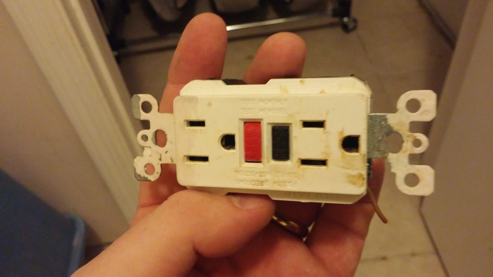
I had a similar demonstration of this theory today. The GFCI/ELCB socket in my downstairs toilet let it's smoke out today. Good job we caught it too otherwise we may not have had a home to live in.


Turns out that there was a loose connection in the return wire. Every time my wife ran her hair dryer it would cause the wires to move under the stress of the current load. The return (a white wire here in the US) would then disconnect itself then reconnect itself causing lots of sparks and arcing and burning. The result was that both the wires and the socket would get hot and so release their smoke.


Good job we caught it. Or rather my dog Rascal caught it. He heard the GFCI arcing then ran into the toilet and started scratching at the wall. It was only when he started barking drawing me into the room that I saw the problem. GOOD DOG!!!!! Extra belly rubs for you.


Monday, 20 October 2014

Yaesu FT-817 Go Kit

Yeah, yeah, yeah. We've all seen Go Kits before. But as Go Kits go I think mine is "up there".

I am a fan of the Pelican case. Y'know the ones? Hard plastic water tight cases that can float and take a beating when traveling. They are usually filled with foam and have cutouts for the equipment they hold.


I bought an IM2200 from my local Best Buy electronics store for $100. This seems to be an average price for them. Ebay did not reveal a cheaper price. It comes filled with 2 layers of "pick-n-pluck" foam which allows you to create shapes by pulling squares of foam out.


In the above picture we can see the lower foam layer. I've created cutouts for the mic, mains PSU, PSU cable and antenna tuner cables. The small box in the top right corner is a Wolphi-Link interface. It's like a PSK31 sound card interface but for your cellphone/tablet. It will also get a cutout.


In this picture we can see the upper layer of foam which holds the FT-817, LDG tuner, spare battery, whip antenna and 1:1 balun. The egg box type foam in the lid also pulls out. I can get 25 feet of RG58 and a 50 foot dipole behind it and still be able to close the lid with ease.

Here's a video of me packing it all away into the case https://www.youtube.com/watch?v=NzgnMb5nZo8

Friday, 10 October 2014

Mobile HF antenna install

I have a 2013 Dodge Journey. It's equipped with all bands from DC to light. It has FM, D-STAR, APRS and HF as well as a few non ham facilities. The problem with the car is that the steel its made from is very thin. The roof for example, flexes with the stress of a VHF antenna. So you can imagine what happens with a tall HF antenna?

A common HF antenna mounting solution is to install a clamp style bracket onto the rear liftgate high up as near to the roof line as possible. This is not possible with my car as the rear liftgate is made of plastic. Plastic and antennas don't work together. One needs a rather large amount of metal underneath the HF antenna so as to act as the counterpoise.

Over the 18 months or so that I've had my vehicle I've tried various mounting methods the best of which was a rather large magnet affair that consumed quite a bit of the roof space. This in turn prevented me from using the roof for other purposes.

My friend Kathy, KT2F, has an expression; "Be a man! I'm a man". She is referring to her willingness to drill holes in her new car to mount antennas. She's not wrong. According to my friend Norman, G4WQS, "a good mechanical join makes a good electrical join". Drilling a hole into the metalwork of the car would create both strong mechanical and electrical connections but only where the metal is thick enough.

I needed to replace the brake light on the back of my car today. Removing the light cluster is a simple matter of removing 2 plastic buttons. That's when I saw it. I finally found a spot to mount the antenna. It's not the best place on the car but it has all the other boxes checked.


You can clearly see the grommet where the cable exits the car behind the light cluster. By dumb luck I had a bracket in the junque box that would fit between the light and the car. 4 holes and some rivets later the mount was installed and a SO239 type antenna connector was attached to the mount. The coax feeding the antenna will feed through the grommet into the car and then on to the back of the radio.


As you can see from the completed installation, it is quite tidy. Click the pictures to get a closer look.


The total job took a little over an hour and that included fishing the coax cable from behind the interior paneling in the back of the car. Tests while parked on the drive show a much improved tune time (I have a screwdriver type antenna) and a broader bandwidth. Indeed, I no longer have to keep retuning when on 40 meters (the lowest band the antenna will cover) whenever I go from one end of the band to the other. Band-to-band tuning is also faster. I can now jump from 40 meters to 10 meters without the auto tuning circuit in the radio timing out.

So now I can tell Kathy that I'm "a man".

Saturday, 27 September 2014

Weather satellite pictures update

It was a very fine autumn day today. I spent most of the morning up on the roof messing about with my antennas. One of these said antennas was for my newly built weather satellite receiver chronicled here http://g7ltt.blogspot.com/2014/07/apt-weather-satellite-pictures.html

There are still a few kinks to iron out of the system and computer control needs to be added but you get the idea ...


It seems the clock on my PC is a little off too. I guess I'll be digging into the bowels of RegEdit to force the NTP update to happen sooner.

Take a look at http://www.g7ltt.com/wxsat/ for more pictures and a timetable.

Wednesday, 10 September 2014

GPS mini cape for Beaglebone Black

On a whim I bought a Beaglebone Black. Now what? I need more PC's like a hole in the head. So what to do with it? Nothing came to mind until I discovered one day that my home brewed NTP server had failed. Aha! A quick poke around the net revealed this howto. Stand well back folks.

I've been playing with the Ublox NEO-6x series of GPS receiver modules recently. They are super-simple to use and add to any project. They need only power, antenna and a serial port. So with the GPSRX being so small and simple to use a daughterboard or "cape" (why cape? UnderDog is a Beagle and he wears a cape) for the Beaglebone was a natural fit. (

The board consumes only one of the headers
The board sits on top of the BBB drawing power from it via the raw 5V line. I found that I had to increase the current on the 5V PSU that supplied the board so that I could get a reliable GPS lock but otherwise it worked first time. And as you can see below, my Linux terminal prefers it to the other available servers from us.pool.ntp.org

g7ltt@earth:~/Downloads$ ntpq -p
     remote                       refid            st t when poll reach   delay   offset  jitter
=====================================================================
*time.g7ltt.com             .GPS.            1 u    5   16  377    0.284    0.880   1.543
-tdp-ism01.exped    206.183.22.197   3 u    4   16  377   55.487  -61.764   1.003
+152-ism01.exped   129.6.15.28        2 u    9   64  377   31.547  -69.109   1.229
-upa-ism01.exped   206.183.22.197   3 u   15   64  377   43.276  -68.318   1.557
+810-ism01.exped   128.118.25.12    2 u    6   64  377   38.032  -67.287   1.023

The prototype board in service
The files in Eagle format ...


Friday, 22 August 2014

20dB or 40dB RF Attenuator

I have found that I need an RF Attenuator for my bench. My bench tools are primarily suited to QRP work and so whenever I have to mess with a 35W FM rig I find that my meters and sensors are inadequate. I've killed quite a few bits of test equipment by stuffing 50W of RF into a 5W power meter.

As part of a larger project to create a 0-500MHZ power meter I started with the attenuator. There's nothing special about this one other than perhaps the compact design. It can be either a 20dB or a 40dB device dictated by the resistors you populate it with. Indeed, if you buy the boards from oshpark.com you can make both variations for less than $5.
See how simple it is?

The attenuator will present a 50Ω load to the connected radio and with its 1/4W resistors should be good for small bursts of around 50W of RF. Adding 1/2W resistors should increase the power capability to 100W and allow for longer key-up times at lower powers.

The files are listed below in both Eagle and PDF formats.

20-40dB_RF_Attenuator.pdf
20-40dB_RF_Attenuator.brd
20-40dB_RF_Attenuator.sch