Recently another Yaesu FT-840 HF transceiver came my way. This prompted me to re-post the below article from my now defunct g7ltt.com website ...
DRM with a Yaesu FT-840
I recently came across a Yaesu FT-840 HF Transceiver so I thought I'd have a go at converting it for DRM use. As this is an older Yaesu model it doesn't have a 455KHz IF but rather an 8.62MHz IF. This was going to be a problem as I didn't want to redesign an IF converter. Unlike modern HF rigs FM was an optional extra requiring a board to be installed into the radio. This optional board has a 455KHz IF and uses the ubiquitous MC3357P FM demodulator chip. In theory this mod should work for all radio's that use this chip (eg. Kenwood TS-430).
A while back I ordered a couple of 455KHz-12KHz down converters from I5XWW with a view to converting my FT-847. These converters use a freely available design found in a number of places on the Net. Frankly for the amount I5XWW charges for these pre-built boards it's not worth the hassle of building a converter on a project board. I paid $15 each for them! Having a spare one left over it became the candidate converter board for this modification.
To make the mod you'll need the following items;
RCA phono socket
6" hookup wire
12" RG174 coax
FM-747 FM option board
12KHz IF converter board
Murata CFW455HT 455KHz ceramic filter (optional)
On a clean bench (not like mine) place the radio upright with it's rear sockets facing you. Remove the 5 screws holding down the top case section. Note that there is a large amount of fresh air inside the case. Remove this and save for later ;}.

First lets install the RCA phono socket. This will be where we connect our PC's sound card to. It will present the 12KHz from the IF converter board. Using a 5/32" drill bit CAREFULLY drill a pilot hole below the air vent at the left hand end of the back panel. Take care to place the hole high enough so that the new socket will not foul any of the components on the board below. Once you are happy with the placement of the pilot hole drill out the pilot hole such that it will accept your RCA socket (usually 1/4"). Finally mount your socket.

Now would be a good time to install the optional CFW455HT 455KHz ceramic filter. The supplied filter on the FM board is somewhat wide and may produce diminished results. You don't have to do this mod but it might help eek out those harder to receive signals. Remove the supplied 455 filter from the FM board (the white square to the left of the board on my picture) and install the new one in its place. The replacement part is pin compatible.
Lets attach the IF converter board to the FM board. I attached my converter directly to the back of the FM board using off-cut resistor legs which I found kicking around my bench. Attach the IF IN on the converter to pin 5 on the MC3357P FM demodulator chip (the long black one). You can pick up 9V on pin 3 of the large white connector and ground can be had either on pin 1 or via any of the solder blobs found on the largest green PCB track. Attach a length of RG174 coax from the converter's IF OUT to the back of the RCA phono socket you installed earlier.

Re-install the FM board back into the radio.

Replace the top cover and 5 screws. Don't forget to put the fresh air back ;}

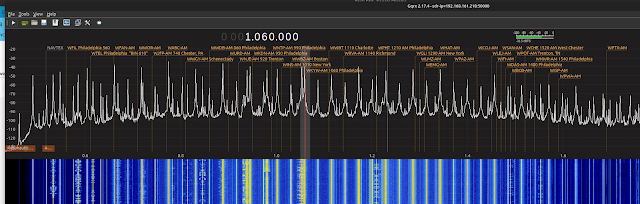
Finally, test it out! Make sure that you check the "Flip Input Spectrum" checkbox in your software. Below are some screen shots and log printouts from the DReaM software.


>>>>
Dream
Software Version 1.10.6cvs
Starttime (UTC) 2008-04-06 15:35:15
Frequency 9800 kHz
Latitude 40.49'N
Longitude 74.34'W
Label RCI
Bitrate 17.16 kbps
Mode B
Bandwidth 10 kHz
MINUTE SNR SYNC AUDIO TYPE
0000 18 300 3000/10 0
0001 25 150 1500/10 0
0002 23 150 1500/10 0
0003 20 150 1500/10 0
0004 17 150 1437/10 0
0005 17 93 885/10 0
CopyWrong 2008 Mark A Phillips, NI2O. All lefts offered.