Wednesday 23 October 2024

Satellite Exploits

 This is a reprint of a few pages from my old g7ltt.com website originally posted in 2002 ...


Firstly lets look at my station. I own the ubiquitous Yaesu FT-847 transceiver. This radio is very commonly found in the stations of many a satellite enthusiast. I have beam antennas for 2mtrs, 70cms and an MMDS down-converter with dish for 13cms (2.4GHz) all of these antennas are mounted on a cheap azimuth and elevation rotator arrangement by Satelectronics.

I have owned this radio for about a year with the intention of getting active on the satellite bands and was finally able to install my antenna system onto my new house in the early summer of 2002. All was not well. I bought one of the first Sat-El rotor systems that were made and it came with a few surprises. Firstly, the software was severely lacking. So much so that I took to developing my own program so that I could make my satellite prediction software control the antennas. QA was also a serious issue. One of the 2 rotators wouldn't work. After several trips to the roof and almost 6 weeks in waiting I finally got a replacement rotor. Having proved that the new one worked I took it apart to compare it with the broken one. The broken one was missing a very large capacitor! It never worked so how could it have passed the manufacturers QA process?


Aligning the antennas was another pain. The antennas must be accurately mounted onto the rotator so that when the rotators think they are looking at the Pole Star the antennas are too. In this way whenever the software controlling the rotators wants to look at a given point in the sky the antennas will correctly look there. This was not an easy task. It took me almost 6 months to complete this stage of the alignment. I couldn't seem to get the rotators to line up with anything.

A few nights ago I was watching "The Dish" on video. Its the story of the Parkes Radio Telescope in Australia. This was the dish that brought the TV pictures of Neil Armstrong's Apollo 11 moon walk back to the world. The story told in the movie is apparently true and it chronicles the goings on during the 2 weeks around the moon walk. Parkes was the only dish in that part of the world capable of receiving the pictures as the moon was only visible from Australia at the time. Well Parkes computer had a problem just a few hours before the big event and they lost contact with the space craft. After an hour of bluffing NASA about land line problems they finally found the space craft by randomly pointing the dish at the moon and waving it around a bit. This gave me an idea!!

So picture the scene. Its 10:30PM. Its dark. Its DAMN cold. The moon is out. Mark is on the roof trying to work out why his antennas are not pointing at the moon when he tells them too. I figured that I could align the antennas with the moon as my point of reference rather than the Pole Star. I can see the moon. I don't know what the Pole Star looks like. I start by guestimating the amount of error between my antennas and the moon's location. I guess 20 degrees. I go down to the basement where I control them from and fiddle with the settings. I go back up onto the roof. I reckon I made it worse. I go back down to the basement. And so on for about half an hour.

I'm getting cold and annoyed. It's getting late and the neighbors dog keeps barking at me up on the roof. I retire to the bedroom to spend some time with my wife before she forgets what I look like. On the way I fall over my laptop computer. A light goes on! I have a wireless network card in my laptop and some remote control software on my computer in the basement. Quick as a flash I'm back on the roof with my laptop. Now I can see what I'm doing!! Within about 5 minutes I was able to align the antennas so that they pointed at the moon. As the antennas are only about 6 feet above the roof of my house I was able to look from the back of them up to the moon and see that they were perfectly lined up. Back down the ladder and off to bed.

Sunday morning and I'm up early and down in the shack. I run up Nova (satellite tracking program) on my computer and find that I'm just in time for a PacSat pass. I instruct my antennas to point to it. A quick check of  Amsat's Operational Satellites page tells me what frequency I need to listen on. Sure enough, there's a whole bunch of data being transmitted. Result! My antennas are looking at a satellite. I don't have anything set up do receive the data so I just listen to it. Not quiet 10 minutes of data was heard here at KC2ENI QTH.


Next up was a crack at AO-40. This is what I started building my satellite system for. I have an MMDS down converter and a 3 foot BBQ grill dish (more about this here) which allows me to listen to the 2401MHz band. This is where all the activity is now as AO-40 has had some sort of unexplained accident which killed off all its other facilities. Sure enough when the satellite came around later that day I was hearing some hams sending each other SSTV pictures. I tried to decode the pictures but I wasn't able to get a good enough signal from the satellite. I was able to decode the telemetry beacon with some success as you can see from the screen capture above.

You can see I was only getting about 40% of the data packets from the telemetry beacon. I'm not sure quite why that is but I suspect that it has something to do with interference from all the 2.4GHz (2401MHz) gizmos we have around the house like our wireless network and some CCTV cameras.

On the next pass I'll turn all the 2.4GHz stuff off and see of it makes an improvement on the telemetry. If so it looks like I'll be spending a lot of time hard wiring the network devices to the main switch here in my shack.


Thursday 10 October 2024

It [still] Buggers Other Channels

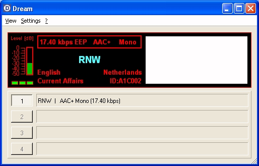
 A few years back I presented an essay at the SWLFest titled "Whatever Happened to Digital Radio?" The gist of it was that Digital Radio was already on the decline in the US having failed to gain any market traction. The story is the same worldwide on shortwave too. 

Unlike other markets around the globe the US uses a product from Ibiquity called In Band On Channel. Ibiquity has been bought and sold a few times since the release of IBOC. Its product name was made a little more friendly by the phrase "HD Radio" giving the illusion that the audio quality was superior to the existing traditional AM and FM systems

Over time the IBOC system gained the nickname "It Buggers Other Channels". It's easy to see why. Take a look at the below screenshot taken from my SDR software. I have an Afedri SDR-Net connected to a MLB-30 active loop antenna. I spotted this signal while looking for something else.

It's 30KHz wide!!  AM stations in the US are normally placed into a 10KHz slot. There is a vacant 10KHz slot either side of them (called "guard channels") which are usually reserved for stations in other markets thus allowing a kind of jigsaw puzzle whereby the various markets fit into each other without interference. 

So a signal 30KHz wide would invade both the guard channels on either side of the allotted frequency. The IBOC signal is injected in "wrapper" mode whereby the digital data is sent in 2 carriers either side of the main AM signal. In the above picture an AM carrier can clearly be seen in the right hand data bundle (the square thing to the right of the red line). Listeners to the station on buried by the data signal will hear a rushing noise along with their normal station.

Perhaps this interference is why IBOC is on the decline? Its the same story on the FM band too. A scan of my local AM band (15 miles NW of Philly) reveals just 3 stations using IBOC down from 15 just a few years ago.

Tuesday 1 October 2024

NinoTNC to Yaesu VX-6R wiring

Some folks have asked me to document the wiring/pinout for my  NinoTNC/Yaesu VX-6R cable. See the below drawing. It is based on a pre-terminated cable I got from Amazon .


Friday 24 February 2023

Upgrade your old TNC to a USB interface

With the current resurgence of Packet Radio I decided to dust off my old Packet Radio Terminal Node Controller (TNC). There were untold thousands of these made in the late 80's and early 90's and to this day can be found at junk sales and hamfests for very modest prices.

One of the issues facing us today is that these modems typicaly used an RS232 serial port to communicate with the host computer. Take a look at your computer. Do you have an RS232 port? Most likely not. They have gone the way of the printer port and the dinosaur. Everything has moved over to USB.

The upgrade is very easy requiring only a USB-TTL interface commonly used to program the Arduino and other like microprocessors. The interface connects to the TTL facilities on the rear of the TNC.


The wiring is trivial. Using some female DuPont connector wires connect the 2 devices together as follows...
USB                             TNC
GND -------------------- GND
TX   -------------------- TX
RX  --------------------  RX


Set up your terminal program to reflect the port and speed settings reqired by your TNC then turn it on.


Monday 14 February 2022

Adventures in QRP

 I've been slowly getting my QRP portable station together. Just before having brain surgery I bought an mcHF QRP radio kit from M0NKA (not a clone or Chinese built rip off). My idea was to build it while recovering from the surgery as a way to prove there was no lasting damage. Things did not go quite to plan and only now some 3 years later am I finishing the radio. Along the way I lost some of the parts including the knobs and the rubber buttons. It also didn't quite work when I gave it a test drive.


Suspecting shoddy workmanship on my part I went back over my work. As far as I could tell it was all good. In conversation with the gang over on the mcHF mailing list it was suggested to me that it might not be my work that's at fault and to check the factory installed components too (the kit comes with many surface mounted parts pre-soldered). Following the alignment procedure I was able to track down the issue to the band pass filter arrangement. I again checked that I had wound the filter coils properly and that they were connected to the PCB. I then progressed to the pre-installed relays that switch the various filters off and on. BINGO. Dry joints abound. Re-flowing the relay's solder joins with my iron yielded a working radio.

I was able to buy some rubber buttons for the radio via eBay but not the knobs. Owning a 3D printer is often a bonus in situations like this. A quick search on thingiverse.com revealed quite a large collection of parts for this radio that I could print including some knobs. That problem is now solved. I later printed a matching tuning knob so that all the knobs are the same colour.

But what about an antenna? In the end I decided to build this one from a radio club that's based in Hawaii. Its a simple end fed random wire antenna with a 9:1 transformer to help with the matching.


This really was a junk box build. I recovered the iron core from an old UPS that my employer was throwing out. In its previous life the core was part of the 24-120V inverter circuit. I was even able to reuse some of the wiring from the old UPS to wind the transformer onto the core.

Again, my 3D printer was pressed into service. Trolling through Thingiverse.com again I was able to find an enclosure for this part of the project. I added 35 feet of speaker wire that was kicking around and was able to complete the project with other supplies form my apparently well stocked junk box. The only thing I had to buy was #6-32 nuts and bolts. They were just $1 at the local WalMart.

Here's a video of me testing the whole setup from the parking area at the back of my apartment building. 

I have this LiFePO4 battery which is about half of the weight of other lead acid batteries of the same size. Plus, its LiFePO4 technology which will actually save me money in the long term as I'll get more life from it. 


I think I'll be printing this carrier for the battery too.


Tuesday 25 January 2022

Crypto mining on an Arduino

Yes. You read that correctly. Crypto mining on an Arduino.

I recently discovered something called Duino Coin. It's a proof of concept crypto currency. But unlike other currencies where you need massive mining rigs to produce just a few $$$ before you pay for the electricity and hardware, this one uses very modest micro processors. In fact if you use higher end hardware to mine this coin you get a penalty and the reward drops significantly.

I'm using a method called I2C mining. This is where a handful of miners are connected together via an I2C bus and then another device handles the connection to the network. Very similar in setup to a traditional rig where a load of graphics cards are plugged into a PC. 

You cannot buy hardware for this project and so I designed my own circuit board. It uses common off the shelf parts. 5x Arduino Nano's (ATMEGA328), 1x Wemos D1 (ESP8266) and a power supply (MP1584). The D1 handles the WiFi connection and the communication with the Arduino's. The Arduino's do the actual mining.


This is what I came up with and it works very well. Each miner gets about 250 hashes a second.

Friday 22 January 2021

GL-INET AR750 conversion to 5VDC

I own one of these Travel Routers. It's great for connecting multiple things to the single Internet feed in a hotel room or camp site. The problem is that it uses a USB power supply and if one does not use the correct cable the router becomes unstable. This is due to the voltage losses in the thin wire used in cheap USB cables. The router is quite thirsty and so requires a cable that can deliver a good half an amp.

GL.INET AR740 Travel Router

I want to use this router for camping. I want to have this router be the Access Point that my phone and laptop and TV connect to. In turn this router will connect (usually by WiFi in WISP mode) to whatever Internet I can find. To this end I need to power it from my 12V camping batteries or solar panels.

One of the optional extras for this router is a Power Over Ethernet (POE) board which will take the 48V from your POE capable network switch and convert it to the 5V needed to power the router. 

POE Adapter

I opened up the router and found the pins that would receive the 5V from the above POE board. This discovery was greatly helped by the below picture that I found on the manufacturers website.

Now that I have established how to connect 5V to the board I need to come up with a 12V to 5V DC-DC power supply. Luckily Amazon is full of them. For a previous project I bought some LM2596S variable DC-DC power supplies. These are available from all the usual online places such as Amazon and Ebay for around $1 each.
LM2596S DC-DC "buck boost" converter.


A word of warning; before connecting this power supply to your Router (or Raspberry Pi etc) make sure to set the output voltage to whatever you need it to be.  This can be achieved by connecting your power source to the input then turning the screw on the variable resistor (the blue block thing) whilst measuring the output with a volt meter. I set mine to 5.02V.

Next was a session with my 3D printer to create an enclosure. Thingiverse.com was my friend here. However I had to print a second power supply case as the lid to the first one would not fit. The capacitors on the board were too tall to allow the lid to fit.

DC-DC converter in 3D printed case

Time to test it all. I wired the power supply into the router and gave it an initial "smoke test". No smoke was observed this time. Everything seemed to work as expected.

DC-DC power supply connected to the router

DC-DC power supply and router wired together

All wrapped up with in their respective cases

The final step was to install in onto the electrical board that I use when camping. The board holds the solar charger, fuse board, 110V inverter and battery charger. This seemed like a logical place to install the router as power is available right there. I also installed the POE injector for a TP-Link WiFi bridge with high gain antenna that can be remotely placed (for example, on my portable radio mast) to bring in the WiFi signal from further afield should it be needed. 

Router installed on power board

A quick trip to my local WholeFoods Market (where they have free WiFi) was made to test the whole system. It worked flawlessly. Here are some screen shots from the test tools I used.